


Controls, LEDs, and Connectors
MVME2500 Installation and Use (6806800L01H)
42
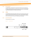
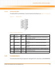
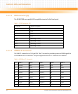
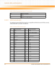
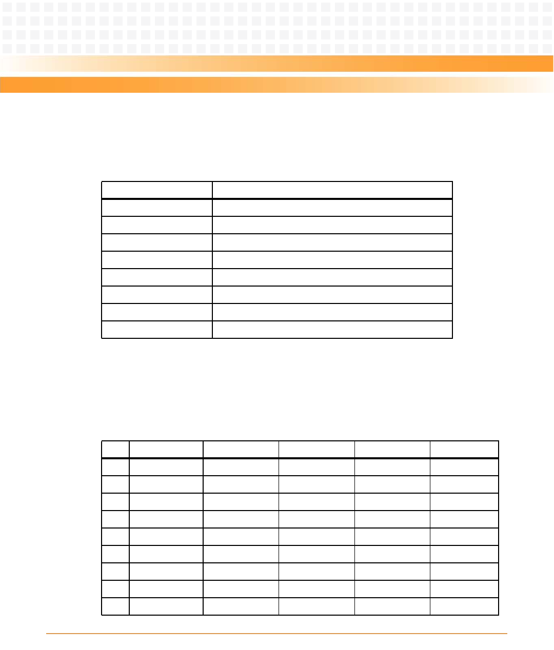
3.4.1.3 USB Connector (J5)
The MVME2500 uses upright USB receptable mounted in the front panel.
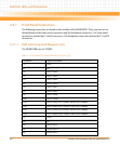
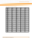
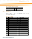
3.4.1.4 VMEBus P1 Connector
The VME P1 connector is a 160-pin DIN. The P1 connector provides power and VME signals for
24-bit address and 16-bit data. The pin assignments for the P1 connector is as follows:
Table 3-5 USB Connector (J5)
Pin Name Signal Description
1 +5 V
2 Data -
3 Data +
4GND
MTG Mounting Ground
MTG Mounting Ground
MTG Mounting Ground
MTG Mounting Ground
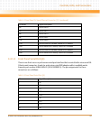
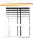
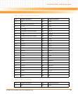
Table 3-6 VMEbus P1 Connector
Pin Row A Row B Row C Row D Row Z
1 DATA 0 BBSY DATA 8 +5V NC
2 DATA 1 BCLR DATA 9 GND GND
3 DATA 2 ACFAIL DATA 10 NC NC
4 DATA 3 BGIN0 DATA 11 NC GND
5 DATA 4 BGOUT0 DATA 12 NC NC
6 DATA 5 BGIN1 DATA 13 NC GND
7 DATA 6 BGOUT1 DATA 14 NC NC
8 DATA 7 BGIN2 DATA 15 NC GND
9 GND BGOUT2 GND GAP NC