Functional Description
MVME2500 Installation and Use (6806800L01H)
77
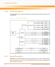
4.17.1 Reset Sequence
The timing of the reset sequence supports each chip reset requirements with respect to the
power supply.
4.18 Thermal Management
The MVME2500 utilizes two on-board temperature sensors: one for the board and the other for
the CPU temperature sensor. The board temperature sensor is located near the dual RJ45
connector near the front panel. The CPU temperature sensor is located near the P2020 CPU.
The MVME2500 thermal management support will interrupt the process only to show the
current board and CPU temperature. This interrupt is routed directly to one of the processor’s
IRQ4.
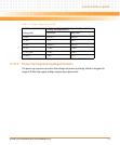
The table below shows the low and high threshold temperature in order for the interrupt to be
asserted.
4.19 Real-Time Clock Battery
A back-up battery based on the CR2325 specification is provided. It helps support the RTC
hold-up requirements that maintain the correct date and time for at least two hours after the
backplane power is switched off.
Table 4-2 Thermal Interrupt Threshold
Board Variant Board Temperature Limit
Board
Temperature Limit
CPU Temperature
Limit
Low High Low High
Standard Variant 0°C to +55°C 0°C 70°C 0°C 90°C
Extended Temperature
Variant
-55°C to +71°C -40°C 90°C -40°C 100°C


