


Controls, LEDs, and Connectors
MVME2500 Installation and Use (6806800L01H)
56
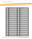
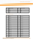
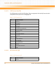
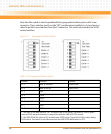
3.4.2.8 Miscellaneous P2020 Debug Connectors
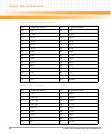
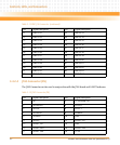
9 NC NC NC NC NC +3.3V
10 GND GND JTAG TDO GND GND GA 0
11 TX0 TX0 - BIST (PULLED
UP)
TX1 + TX1 - +3.3V
12 GND GND GA 1 GND GND PRESENT
13 NC NC NC NC NC +3.3V
14 GND GND GA 2 GND GND I2C DATA
15 NC NC NC NC NC +3.3V
16 GND GND MVMRO
(PULLED
DOWN)
GND GND I2C CLOCK
17 NC NC NC NC NC NC
18 GND GND NC GND GND NC
19 CLK + CLK - NC NC ROOT0
(PULLED UP)
NC
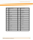
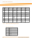
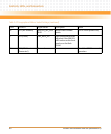
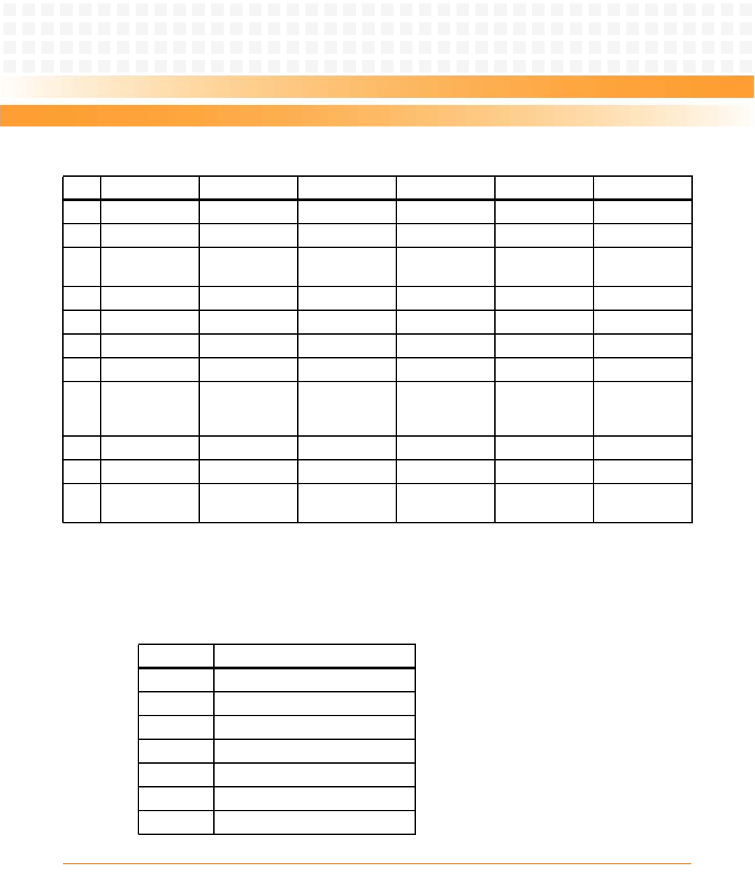
Table 3-17 XMC Connector (XJ2) Pinout (continued)
Pin Row A Row B Row C Row D Row E Row F
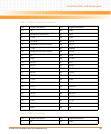
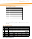
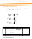
Table 3-18 P20x0 Debug Header
Pin Signal Description
1 MSRCDI0
2GND
3 MSRCDI1
4MDVAL
5 MSRCDI2
6 TRIG_OUT
7 MSRCDI3