


Controls, LEDs, and Connectors
MVME2500 Installation and Use (6806800L01H)
58
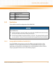
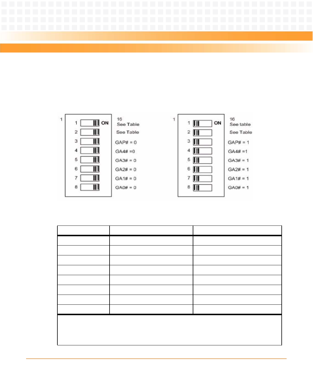
Note that this switch is wired in parallel with the geographical address pins on the 5-row
connector. These switches must be in the "OFF" position when installed in a 5-row chassis in
order to get the correct address from the P1 connector. This switch also includes the SCON
control switches.
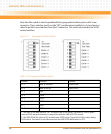
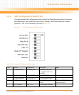
Figure 3-5 Geographical Address Switch
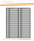
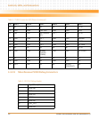
Table 3-19 Geographical Address Switch
Position Function Default
S1-1 VME SCON Auto
1
Auto-SCON
S1-2 VME SCON SEL
2
Non-SCON
S1-3 GAP 1
S1-4 GAP4 1
S1-5 GAP3 1
S1-6 GAP2 1
S1-7 GAP1 1
S1-8 GAP0 1
1. The VME SCON MAN switch is "OFF" to select Auto-SCON mode. The switch is "ON" to select
manual SCON mode whichworks in conjunction with the VME SCON SEL switch.
2. The VME SCON SEL switch is OFF to select non-SCON mode. The switch is ON to select always
SCON mode. This switch is only effective when the VME SCON MAN switch is "ON".