


E-12 UPGRADE 2350A GC S/W AND 2350 EPROMS
MON2000
Replace EPROMS/Reset CPU JULY 2010
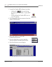
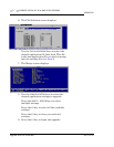
(d) Unplug the TB power supply cord from
its connection at the Card Cage
Assembly power supply.
(e) Loosen the four thumbscrews that
secure the Card Cage Assembly to the
chassis. Then remove the Card Cage
Assembly away from its chassis mount
so that it is easy to work on.
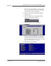
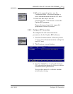
(f) Unplug all cables connected to the
boards in slots 2 through 6 of the Card
Cage Assembly in order to access the
SBC53 CPU Board.
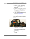
3. Remove the SBC53 CPU Board from slot
number 2 (second from the top) of the Card
Cage Assembly.
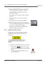
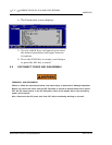
E.6 REPLACE EPROMS/RESET CPU
1. For 2350 GC Controllers, locate the
EPROMs that will be replaced: U18 and
U19. They are near the card-connector edge
of the SBC53 CPU Board.
2. Remove, one at a time, each of the old
EPROMs, and replace each with its upgrade
EPROM.
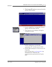
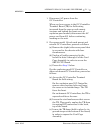
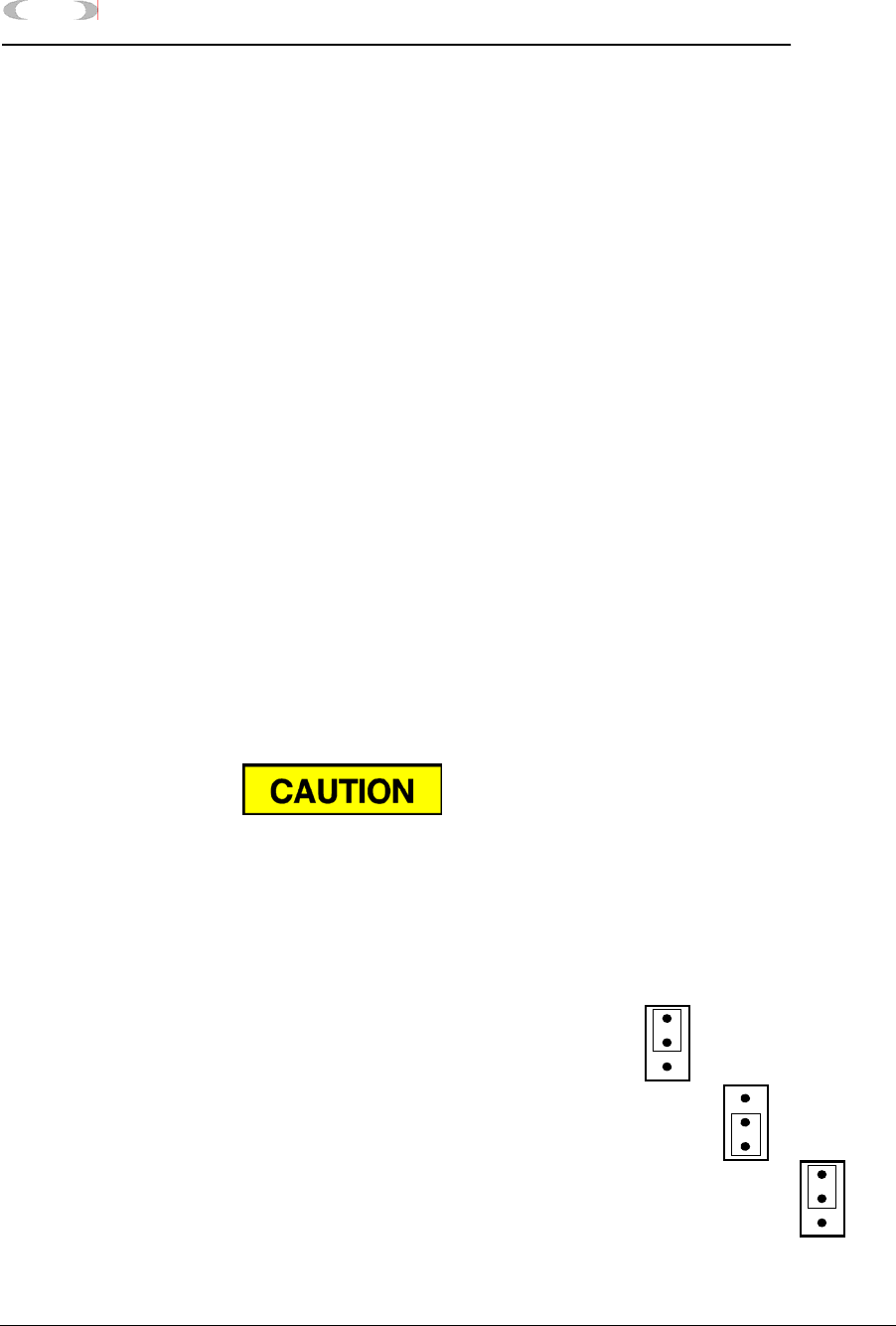
3. Locate Jumper Pin Set J14. It is near the
two EPROMs you have just replaced.
Note that Jumper Pin Set J14 has a single
jumper shorting pins 1 and 2.
Carefully note which EPROMs are labeled ODD and
EVEN and which sockets hold them:
socket U18 EVEN EPROM P/N 8-2350-001
socket U19 ODD EPROM P/N 8-2350-002
1.
2.
3.