


INSTALLATION AND SETUP 2-59
MON2000
JULY 2010 2350A Ethernet Installation
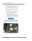
5. Locate the System Interface and Driver
board. It is mounted to the top of the Card
Cage Assembly.
(a) Disconnect the Analog cable from J6 on
the System Interface Board, then
disconnect all CPU cables from the
System Interface Board.
(b) Remove the CPU assembly and install
the COM4A Board, with associated
mounting hardware to J19 and J20 PC/
104 Bus connector on the CPU assembly.
(c) Plug one end of the Ethernet extension
cable (P/N 3-2350-088) into J5 of the
Ethernet assembly.
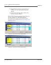
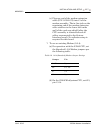
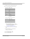
6. The in-line jack on the remaining end of the
Ethernet extension cable attaches to the
lower left inside wall of the card cage shield,
after the CPU assembly is reinstalled and
all cables reconnected to the System
Interface board (see Table 2-7 and Table 2-8
below).
If an option board is already plugged into the PC/104 bus
on the CPU, the ethernet card and mounting hardware
will be installed into the PC/104 connector on the option
board.
If you are using the CSA approved Radicom modem;
ensure that it is the top card in the card cage assembly.
The connection configuration of the Radicom modem
requires installation at the top of the assembly.