


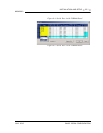
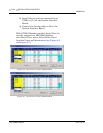

INSTALLATION AND SETUP 2-47
MON2000
JULY 2010 Conversion Process
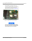
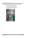
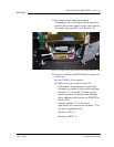
17.For rack mount and panel mount
Controllers, use a flat head screw driver to
remove the access panel on the right side of
the card cage assembly (see Figure 2-3).
Figure 2-3 Right Side View Rack and Panel Mount Units
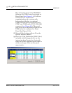
18.Inspect or change the DIP switch settings as
necessary.
(a) See Table 2-5 as a guide.
(b) Make sure you record in the GC
Controller's maintenance records any
changes you make to the switch settings.
• Switches "1" through "5" form a 5-bit
binary number for setting the Modbus
slave address (also known as COM ID or
Device ID.)
• Switch number "1" is the least
significant bit, and switch number "5" is
the most significant bit.
Switch to ON = 1
Switch to OFF = 0