


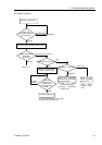

4. Troubleshooting (DeviceNet)
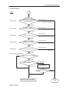
♦ Causes of Error
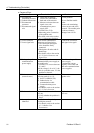
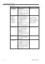
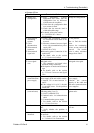
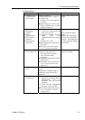
Possible Cause Examination Method Countermeasure
{ Voltage drop of
communications
power supply
Measure voltage of
communications power supply at
the master unit.
→ Normal: 11V or more between
V+ and V-
z If the voltage is 11 to 14 V, the
unit is a possible cause. Fix the
problem on the unit.
Check voltage of the power
supply.
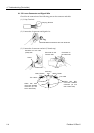
{ Disconnected
terminating
resistors
{ Cable
disconnection
{ Disconnected
connector
{ Disconnected
signal wire
(1) Check that terminating
resistors are connected to both
ends of the network.
(2) Measure resistance between
signal wires with
communications power supply
OFF.
→ Normal: 50 to 70 Ω
z Measuring point: Connection of
the master
z For detail, refer to the section
4.1.3.1 Connection Problem.
Fix the problem.
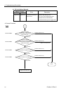
How to find the trouble
point:
Remove the terminating
resistor on one end of the
network. The trouble point
is where resistance changes
from 120 Ω.
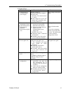
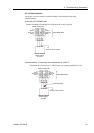
{ Loose connector
{ Loose signal wire
Check for the connection of
connectors and signal wires.
→ The connectors and signal
wires should be firmly
connected.
z Checkpoint: Between the master
and its slaves
z For details, refer to the section
4.1.3.2 Loose Connector and
Signal Wire.
Connect the connectors and
signal wires again.
{ All slaves power
OFF
Measure the power voltage of the
slaves.
(It should be within the range of
sufficient voltage for the slave
operation.)
Supply power to the slaves.
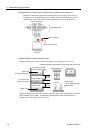
{ Master unit
configuration
(1) Start applicomIO Console
application and check that the
configuration has no
difference with the network
condition.
(2) Check that the configuration
data were written in flash.
z For details, refer to the section
4.1.3.6 EPSON RC+ Master
Configuration.
Change the configuration.
Fieldbus I/O Rev.6 95