


4. Troubleshooting (PROFIBUS DP)
4.2.1 Examining a Problem
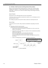
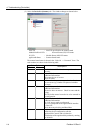
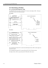
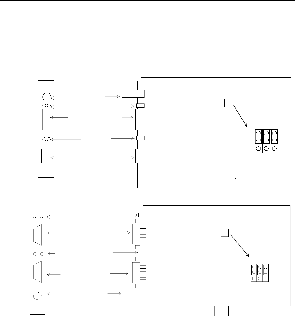
4.2.1.1 Scanner Board Diagnostic LEDs
The PROFIBUS DP board used with EPSON RC+ has two status display LEDs. The layout
of the LEDs is shown in the following figure.
PCU-DPIO
C0 C1 C2
JP1
JP1
0
1
PROFIBUS-DP Port
LED (2)
(Not in use)
RJ45 Connector
(Not in use)
4-pin Terminal
Watchdog Port
(Do not use this port.)
Jumper for Board Address
Status Display LED (2)
PCI-DPIO
C0 C1 C2
JP1
JP1
0
1
Configuration Port
Communication Status LED
Male 9-pin D-Sub
Port for Board Configuration
Status Display LED (2)
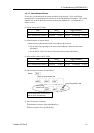
Left: Communication Status LED
Right: Physical Error LED
Jumper for Board Address
Female 9-pin D-Sub
PROFIBUS DP Port
4-pin Terminal
Watchdog Port
(Do not use this port.)
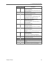
The Communication Status LED is on the left and the Physical Error LED is on the right seen
from the rear panel.
The Communication Status LED is expressed by the ST LED (ST) in this section.
The Physical Error LED is expressed by the BF LED (BF) in this section.
112 Fieldbus I/O Rev.6