


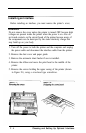

Inserting the Interface Board
1. Remove the upper case of the printer, following the steps described
in the previous section.
2. Remove the blanking plate above the parallel connector (as shown
in Figure F-5) to allow access to the new interface connector when
the case is reassembled.
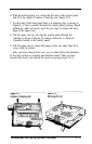
3. Locate the three supports on which the interface board will rest, and
the screw at the rear of the circuit board labelled FG. These are also
shown in Figure F-5. The screw marked FG is the connection for the
frame ground wire. Connect the frame ground wire before inserting
the interface.
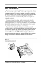
4. Insert the interface board beneath the printer mechanism, as
indicated by the lines in Figure F-6, and plug it into the connector
marked CN2 on the main circuit board of the printer.
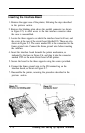
5. Secure the board to the three supports using the screws provided.
6. Connect the frame ground wire to the FG terminal tag on the
interface board, as shown in Figure F-7.
7. Reassemble the printer, reversing the procedure described in the
previous section.
F-6
Choosing and Setting Up Optional Interfaces