SEGMENT OPTION GENERATOR SOG62XX
S1C62 FAMILY EPSON VI-3
DEVELOPMENT TOOL REFERENCE MANUAL
3 OPTION LIST GENERATION
3.1 Example of Option List
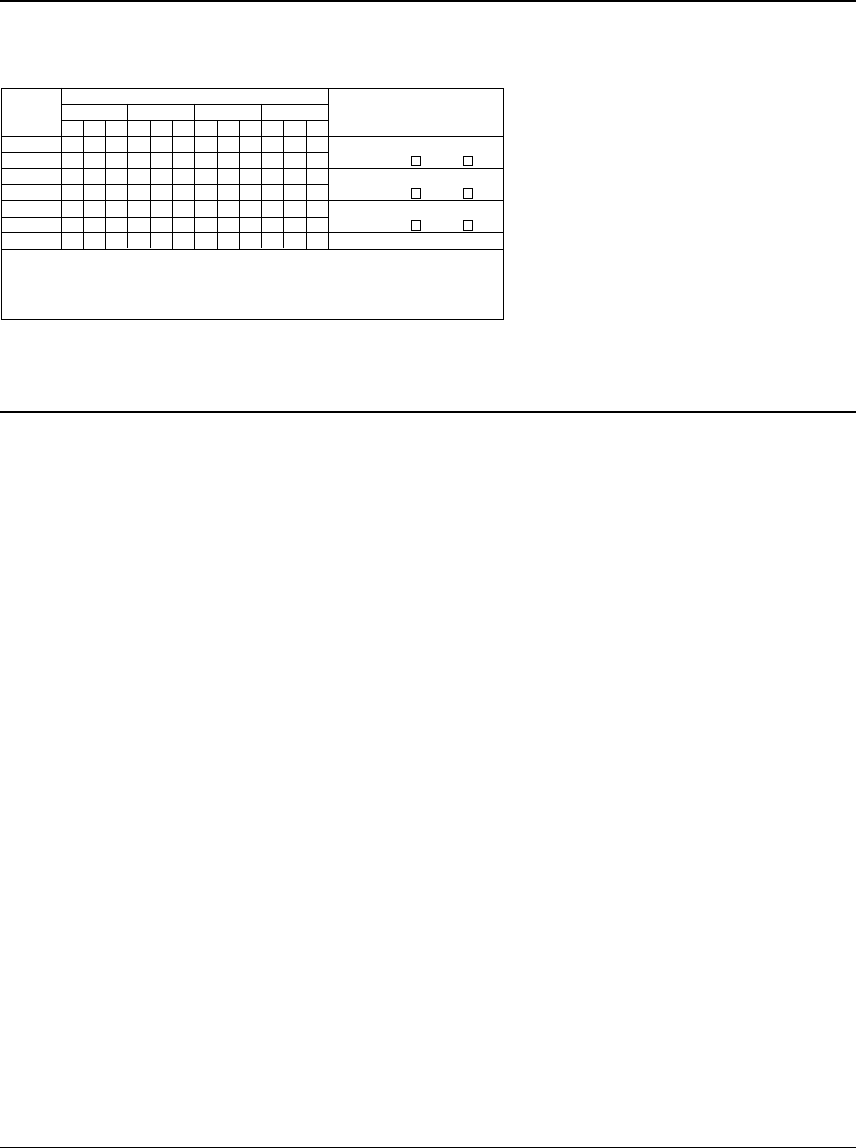
The following table shows an example of the option list in case of the four commons. Refer to the
"S5U1C62xxxD Manual" for the option list of each model.
Example of option list
Multiple specifications are available in
segment option item as indicated in the
following example. Using "S5UC62xxxD
Manual" as reference, select the specifica-
tions that meet the target system and
check the appropriate box. Be sure to
record the specifications for unused ports
too, according to the instructions pro-
vided.
Furthermore, write the segment memory
addresses as well as the selected output
specifications.
Create a segment option source file by
using the option list as reference.
OUTPUT SPECIFICATIONCOM0 COM1 COM2 COM3
ADDRESS
SEG0
SEG1
SEG2
SEG3
SEG4
SEG5
:
LHDLHDLHDLHD
SEG output
DC output
SEG output
DC output
SEG output
DC output
:
C
C
C
:
P
P
P
TERMINAL
NAME
Legend: <ADDRESS>
H: High order address
L: Low order address
D: Data bit
<OUTPUT SPECIFICATION>
C: Complementary output
P: Pch open drain output
3.2 Segment Ports Output Specifications
For the output specification of the segment output ports (SEG0–SEG*), segment output and DC output can
be selected in units of two terminals. When used for liquid crystal panel drives, select segment output;
when used as regular output port, select DC output. When DC output is selected, either complementary
output or Pch open drain (Nch open drain is set depending on the model used) may further be selected.
However, for segment output ports that will not be used, select segment output.
■ When segment output is selected
The segment output port has a segment decoder built-in, and the data bit of the optional address in the
segment memory area can be allocated to the optional segment.
The segment memory may be allocated only one segment and multiple setting is not possible.
Segment allocation is set to H for high address, to L for low address (0–F), and to D for data bit (0–3)
and are recorded in their respective column in the option list. For segment ports that will not be used,
write a hyphen ("-") each on the H, L, and D columns.
The allocated segment displays when the bit for this segment memory is set to "1", and goes out when
bit is set to "0".
■ When DC output is selected
The DC output can be selected in units of two terminals. Also, either complementary output or open
drain output is likewise selected in units of two terminals. When the bit for the selected segment
memory is set to "1", the segment output port goes high (VDD), and goes low (VSS) when set to "0".
Segment allocation is the same as when segment output is selected but for the while the segment
memory allocated to COM1–COM3 becomes ineffective. Write three hyphens ("---") in the COM1–
COM3 columns in the option list.
Note The configuration of the common terminals (COM0–COM3) may vary depending on the model.


