


Section 2: Getting Started 2-3
70055MP Revision D February 3, 2000
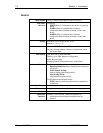
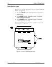
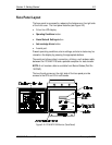
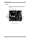
Face Panel Layout
The face panel is accessed by releasing the fasteners on the right side
of the front cover. The front panel features (see Figure 2-2):
• A four-line LCD display.
• Operating Conditions button.
• Alarm Status & Settings button.
• Acknowledge Alarm button.
• A serial port.
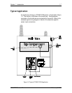
Present operating conditions, alarm settings, and alarm status may be
viewed on the display by pressing the appropriate buttons.
The serial port allows direct connection, utilizing a null modem cable,
between the LTC-MAP 2130 and a portable computer for data transfer.
NOTE: A null modem cable is available from Reuter-Stokes (Part No.
10101MP).
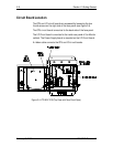
The two thumb screws on the right side of the face panel provide
access to the CPU and I/O circuit boards.
Figure 2-2: LTC-MAP 2130 Monitor (Face Panel)