


Section 3: Installation 3-13
70055MP Revision D February 3, 2000
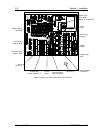
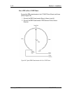
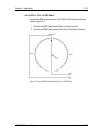
-5 to +5 VDC or -10 to +10 VDC Power
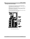
Connect the OEM potentiometer to the LTC-MAP Circuit Board, as follows
(refer to Figure 3-7):
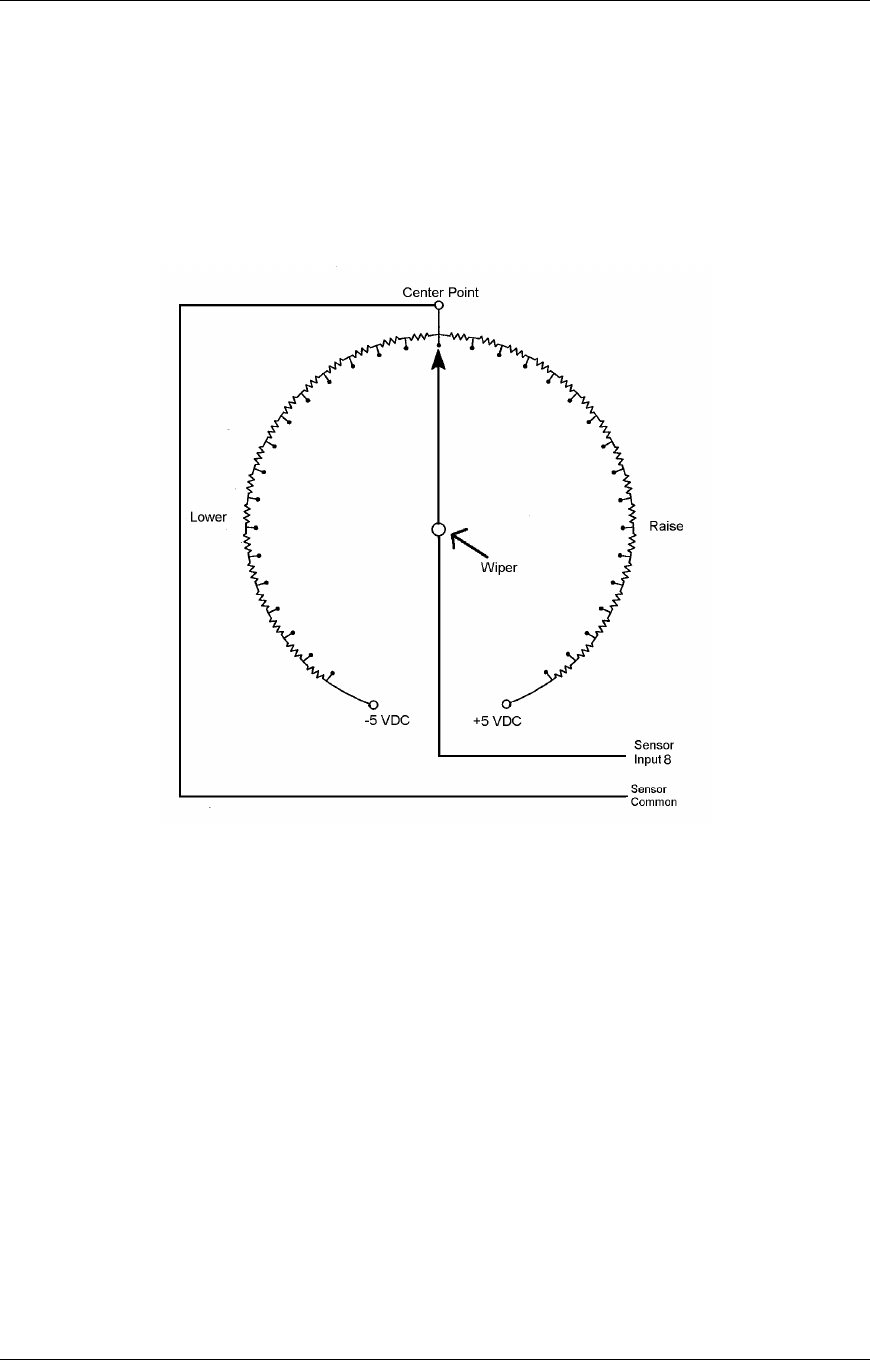
1. Connect the OEM Potentiometer Wiper to Sensor Input #8.
2. Connect the OEM Potentiometer Center Point to the Sensor Common.
Figure 3-7: Typical OEM Potentiometer with -5 to +5 VDC Power