


70055MP Revision D iii February 3, 2000
Table of Contents
Section 1: Introduction
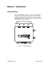
Product Overview......................................................................................................................................................1-1
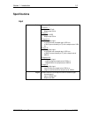
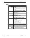
Specifications...........................................................................................................................................................1-3
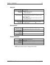
Input...................................................................................................................................................................1-3
General...............................................................................................................................................................1-4
Electrical...........................................................................................................................................................1-5
Environmental...................................................................................................................................................1-5
Physical Enclosure..........................................................................................................................................1-5
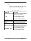
Available Options......................................................................................................................................................1-6
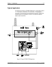
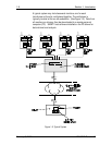
Typical Application..................................................................................................................................................1-7
Manual Conventions................................................................................................................................................1-9
Product Labels..........................................................................................................................................................1-9
Section 2: Getting Started
Receiving Inspection................................................................................................................................................2-1
Customer Support/Service.......................................................................................................................................2-1
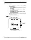
Front Cover Layout....................................................................................................................................................2-2
Face Panel Layout....................................................................................................................................................2-3
Operating Conditions Button.............................................................................................................................2-4
Alarm Status & Settings Button.........................................................................................................................2-4
Acknowledge Alarm Button................................................................................................................................2-4
LCD Display...........................................................................................................................................................2-5
Serial Port ..............................................................................................................................................................2-5
Circuit Board Location.............................................................................................................................................2-6
I/O Board ...............................................................................................................................................................2-7
Power Supply Board ............................................................................................................................................2-8
CPU Board .............................................................................................................................................................2-9
Communications.....................................................................................................................................................2-10
Section 3: Installation
Selecting a Location................................................................................................................................................3-1
Mounting the Monitor..............................................................................................................................................3-2
Cable Installation......................................................................................................................................................3-3
I/O Board Configuration Jumpers..........................................................................................................................3-4
Channel Configuration........................................................................................................................................3-4
Modem Power Supply Configuration Jumper..................................................................................................3-5
Alarm Configuration Jumpers ............................................................................................................................3-6
Ground Jumpers...................................................................................................................................................3-6
Wiring.........................................................................................................................................................................3-7
Overview.................................................................................................................................................................3-7
Wiring the Sensors.............................................................................................................................................3-10
Wiring a Tap Position Indicator......................................................................................................................3-11
OEM Potentiometers......................................................................................................................................3-11
After-Market....................................................................................................................................................3-16
Wiring the AC Voltage Inputs...........................................................................................................................3-17
Wiring the AC Current Inputs...........................................................................................................................3-17
Wiring the Digital Inputs...................................................................................................................................3-17
Wiring the Annunciator Outputs.....................................................................................................................3-18
Wiring the Internal Heater................................................................................................................................3-19
Wiring Power.......................................................................................................................................................3-19