


Section 3: Installation 3-11
70055MP Revision D February 3, 2000
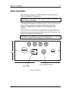
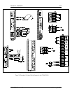
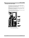
Wiring a Tap Position Indicator
OEM Potentiometers
The OEM potentiometer is a voltage divider containing a resistor string.
Each position on the string represents a tap position. In the examples in
this Section, the potentiometers have thirty three positions containing thirty
two 40-ohm resistors. The actual number of positions and number and
values of resistors may be different on your potentiometer.
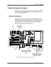
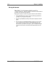
The power supplied to the OEM potentiometer depends on the utility. The
variations include:
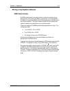
• -5 to +5 VDC or -10 to +10 VDC.
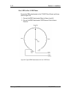
• 0 to +5 VDC or 0 to +10 VDC.
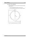
• No voltage (connect with LTC-MAP power).
Determine the voltage across your potentiometer and follow the
appropriate wiring instructions.
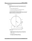
In general, two signals are utilized between the OEM potentiometer and the
LTC-MAP. The signal is a linearly varying DC voltage (+10 V maximum).
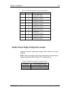
For proper tap position recording by the LTC-MAP, the linearly varying DC
voltage from the OEM potentiometer must have a uniform increment for
each tap position. For example, a potentiometer used for a 33 tap device
(16 lower, 16 raise, and neutral) with a 10 Volt drop across the entire bridge
must show a 10V/32 = 0.3125 V change per tap step on the potentiometer
wiper.