


70055MP Revision D February 3, 2000
Section 5: Troubleshooting Procedures
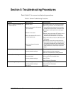
Refer to Table 5-1 for common troubleshooting procedures.
Table 5-1: Common Troubleshooting Procedures
Condition Possible Cause(s) Corrective Action
Incorrect Temperature Reading on a
4-20 mA Channel.
Defective sensor.
Loose wiring connection from sensor
to circuit board
Defective circuit board.
Ribbon cable between CPU and I/O
circuit boards loose.
Ground loop exists with another
connection.
Swap suspect sensor with a known good sensor.
Check wiring connection from the sensor to the
circuit board; ensure that the wire is correctly
inserted into the screw down connector block.
Swap suspect circuit board with a known good
board.
Temporarily move the suspect RTD sensor wire to
an unused 4-20 mA channel to determine
whether fault follows sensor or circuit board.
Inspect ribbon cable connection at CPU board and
at I/O board.
Systematically remove other connections to the
circuit board until the cause of the loop is found.
For example, problems may be caused having
the individual wire (color) order incorrect for the
cable between the control isolator and the I/O
board.
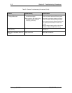
Unrecorded tap change events. Incorrect wiring.
Incorrect parameter settings.
Check wiring diagram and installation.
Check event start and stop parameters.
Check for a minimum motor current parameter.
Incorrect Current Readings. Incorrect installation.
No current present.
Incorrect parameter settings.
Check wiring diagram and installation.
Verify current with a handheld meter.
Check CT Ratio.
Check Calibration Parameters.
Incorrect Voltage Readings. Incorrect wiring.
Incorrect parameter settings.
Power glitch.
Check wiring diagram and installation.
Check Calibration Parameters.
Cycle Power.