


3-18 Section 3: Installation
February 3, 2000 70055MP Revision D
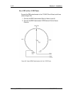
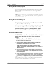
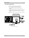
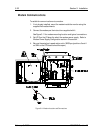
Wiring the Annunciator Outputs
Wire the alarms by connecting the alarm activation signal to the Alarm
normally opened or Alarm normally closed contacts. Refer to Figure 3-5 for
Alarm Contact (Annunciator Output) locations.
NOTE: The signal specification range for the Alarm Inputs are 120 VAC @ ¼
HP, 240 VAC @ 10 A, or 150 VDC @ 10 A. If your signal is different, contact
Support Services as noted on back cover.
Be sure to configure the alarm jumpers (JP18 and JP19) for either normal or
inverted output as required by your application.
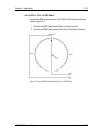
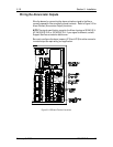
Figure 3-9: I/O Board Terminal Locations