


B-2 Appendix B: Firmware Upgrades
February 3, 2000 70055MP Revision D
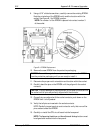
9. Using a 3/16” slotted screwdriver, carefully remove the existing EPROM.
Note the orientation of the EPROM notch and the location within the
socket. See Figure B-1 for EPROM location.
NOTE: Pin number 1 of the EPROM is placed into contact number 3
of the socket.
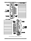
Figure B-1: EPROM Replacement
10. Remove the new EPROM from the protective packaging.
CAUTION: To avoid damage to the component, do not remove the EPROM
from the protective packaging until you are ready to install it.
11. Determine the proper notch orientation and location within the socket.
12. Carefully bend the pins on the EPROM until they align with the socket
contacts.
CAUTION: To avoid damage to the component, do not push the EPROM into
the socket until all pins are perfectly aligned with the contacts.
13. Once all pins are aligned with the socket contacts, push down on the
EPROM until it is fully seated.
14. Verify that all pins are inserted in the socket contacts.
NOTE: Carefully inspect each pin and contact to verify that none of the
pins are bent under the EPROM.
15. Carefully re-install the CPU circuit board into the face panel.
NOTE: The Operating Conditions and Alarm Status & Settings buttons must
be aligned and inserted into the face panel.