I-2 Index
February 3, 2000 70055MP Revision D
F
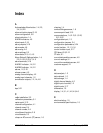
face panel, 2-2, 2-3, 2-4, 2-9, 4-6
front cover, 2-2, 2-3
front panel controls, 1-4
front panel display, 1-4
front panel indicators, 1-4
G
gland plate, 3-1, 3-3
ground jumpers, 3-6
ground lug, 3-7
H
heater, 3-19, 5-2, 5-4
I
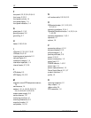
I/O board, 3-7, 3-10, 3-17, 3-22
I/O Board, 2-9, 2-10
incoming power terminals, 2-11
indicator lights, 2-2
installation category, 1-4
intermittent operation, 1-4
internal heater, 3-7, 3-19
L
LCD display, 2-5
LCD Display, 2-3, 2-12
M
magnetic mount RTD temperature sensor,
1-6
maintenance, 1-4
modem, 1-2, 1-4, 1-6, 2-3, 2-8, 2-13,
3-4, 3-5, 3-20, 3-21, 3-22, 3-23
modem power supply, 3-5
moisture sensor, 1-6
monitoring functions, 4-1
mounting dimensions, 3-2
mounting location, 3-1
multiplexers, 1-6, 1-8
N
null modem cable, 2-3, 2-8, 2-13
O
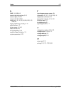
OEM potentiometer, 3-11, 3-12, 3-13,
3-14, 3-15
operating conditions, 2-3, 4-1
Operating Conditions button, 1-4, 2-3, 2-4, 4-
1, 4-2, 4-5
operating temperature, 1-5, 3-1
operation, 4-1
options, 1-6
P
parameter settings, 4-1, 5-1
phone multiplexer, 2-13
pollution degree, 1-5
positive point lead, 3-15
power, 3-19, 5-1
power consumption, 1-5
power fuse, 2-11
POWER indicator, 1-4, 2-2
power input, 1-5
power input protection, 1-5
Power Supply Board, 2-11, 3-7
product overview, 1-1
profile, 1-2
R
receiving inspection, 2-1
relay outputs, 1-4
ribbon cable, 2-9
RTD transmitter, 1-6


