


70055MP Revision D February 3, 2000
Section 4: Operation
Overview
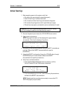
Once power is applied, the LTC-MAP starts monitoring sensor, voltage,
current, and relay timing inputs. Monitoring functions continue
uninterrupted while operating conditions and alarm status & settings are
viewed and during system setup procedures. Channel readings, alarm
status, and current time and date as set from the SAGE host software
package, can be viewed on the LTC-MAP Monitor display.
Refer to the SAGE documentation for detailed channel configuration,
parameter setting procedures, and monitoring capabilities.
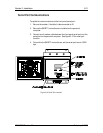
CAUTION: To keep the enclosure weatherproof, close and latch the door
when not using the LTC-MAP. Failure to comply can result in equipment
damage.
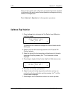
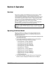
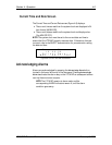
Operating Conditions Button
Operating conditions, including current analog and digital channel
readings and a tap change summary, are displayed by pressing the
Operating Conditions button.
• Pressing Operating Conditions during normal operation displays the first
Analog Channels Screen.
• Pressing Operating Conditions repeatedly during normal operation
continuously scrolls through the following screens:
• Analog Channels 1 through 4 Readings.
• Analog Channels 5 through 8 Readings.
• Analog Channels 9 through 12 Readings.
• Analog Channels 13 through 16 Readings.
• Analog Channel 17 Reading.
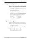
• Digital Channels 1 through 4 Readings.
• Digital Channels 5 through 9 Readings.
• Digital Channels 10 through 12 Readings.
• Digital Channels 13 through 16 Readings.
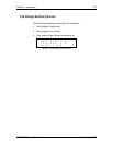
• Tap Change Summary.
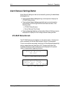
• If Alarm Status & Settings is pressed while any one of the operating
condition screens is displayed, the Status screen is displayed.