


3-10 Section 3: Installation
February 3, 2000 70055MP Revision D
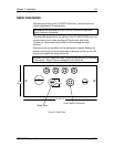
Wiring the Sensors
Refer to Table 1-1 for a list of sensors available for use with the
LTC-MAP 2130 Monitor. Detailed installation information for each sensor is
provided in the referenced documentation.
Some general notes to consider during sensor selection and installation:
• Thermowell RTD sensors require a signal conditioning transmitter to
provide a 4-20 mA output to the monitor.
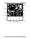
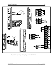
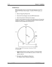
• Figure 3-4 provides Sensor and Input Connection locations on the I/O
board.
• We recommend using #18 AWG shielded, twisted pair wire for sensor
input connections to the I/O board, unless stated otherwise in the
documentation provided with the sensor. Use of shielded twisted pair
improves noise immunity; the shield should be grounded at one end
only.