


Section 3: Installation 3-3
70055MP Revision D February 3, 2000
Cable Installation
After securely mounting the LTC-MAP 2130 monitor, route the input and
output cables back to the gland plate.
CAUTION: Do not apply power to the LTC-MAP 2130 until all input and
output cables are connected.
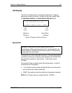
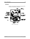
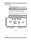
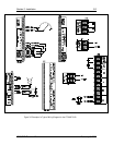
The removable gland plate on the bottom of the LTC-MAP 2130 Monitor has
pre-punched conduit holes (see Figure 3-2) and strain relief cable
connectors. Weep holes are provided to allow drainage of excess
moisture.
Additional holes can be drilled into the gland plate if required. Remove the
plate by removing the two nuts and washers securing it to the monitor. The
nuts are accessed from inside the monitor.
CAUTION: Do not drill additional holes into the gland plate while it is installed
on the monitor. Metal chips can damage the circuit boards.
10.25" (260 mm)
1.25"
(31.8 mm)
.875"
22.2 mm
1"
(25.4 mm)
4.194"
(106 mm)
Weep Holes
Strain Relief Connector
Figure 3-2: Gland Plate