


Section 3: Installation 3-5
70055MP Revision D February 3, 2000
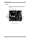
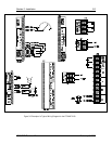
Table 3-1: Channel Configuration Jumpers and Positions
Jumper Position Selected Input
JP1 A
B
5A (CT) Current Input A.
4-20 mA Sensor Input #9.
JP2 A
B
5A (CT) Current Input B.
4-20 mA Sensor Input #10.
JP3 A
B
5A (CT) Current Input C.
4-20 mA Sensor Input #11.
JP4 A
B
50 A (CT) Motor Current.
4-20 mA Sensor Input #12.
JP5 A
B
Voltage Input 1.
4-20 mA Sensor Input #13.
JP6 A
B
Voltage Input 2.
4-20 mA Sensor Input #14.
JP7 A
B
Voltage Input 3.
4-20 mA Sensor Input #15.
JP8 A
B
Voltage Input 4.
4-20 mA Sensor Input #16.
JP9 A
B
Temperature Inside the monitor.
4-20 mA Sensor Input #1.
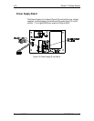
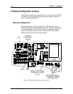
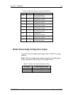
Modem Power Supply Configuration Jumper
Jumper JP12 sets the modem power supply. Refer to Table 3-2 for jumper
positions.
NOTE: Refer to the modem specifications to determine the modem power
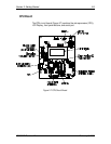
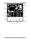
supply requirements. Refer to Figure 3-3 for jumper location.
Table 3-2: Modem Power Supply Configuration (JP12)
JP12 Position Selected Modem Power Supply
1-2 6 VDC
2-3 9 VDC
No Jumper 12 VDC