


Publication 1761-UM006A-EN-P - February 2001
ENI Configuration (Node 248 to 254) 4-7
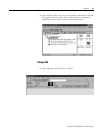
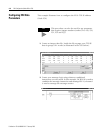
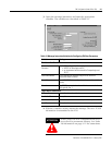
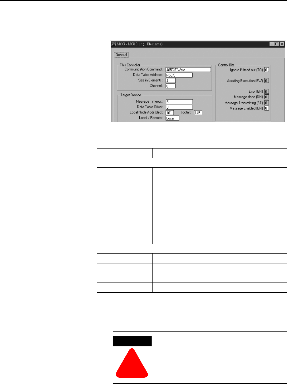
3. Open the message instruction and enter the appropriate
variables. The variables are described in Table 4.1.
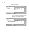
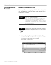
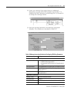
4. With the controller in Run, initiate the message. The new TCP/IP
information is transmitted to the ENI.
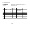
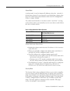
Table 4.1 Message Instruction Variables for Configuring ENI Data Parameters
Variable Setting
This Controller Parameters:
Communication
Command
For the ENI configuration, this must be set to:
• 485CIF for MicroLogix and SLC
• an unprotected write command for CompactLogix and
PLC-5
Data Table Address In this example we are using integer file 50, element 5
(instruction starts at N50:5).
Size in Elements For all ENI TCP/IP data configuration, always set this to 4 (4
words).
Channel The RS-232 communication channel that is connected to the
ENI, typically 0 or 1.
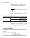
Target Device Parameters:
Message Timeout Leave this value at the default.
Data Table Offset Always 0.
Local Node Addr (dec). This is the destination node address, in this example it is 101.
Local/Remote Always Local.
ATTENTION
!
At this point, the new configuration has NOT
been saved to permanent memory. See Node
248 information on page 4-11 for instructions.