


Publication 1761-UM006A-EN-P - February 2001
5-4 Peer-to-Peer Messaging
Sending a Message to a
Destination Controller
(Nodes 0 to 49)
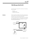
The ENI uses a pair of node addresses to send data messages over
TCP/IP. For data, two sets of addresses are used as illustrated in the
table below. Node numbers 100 to 149 are used to define or store the
actual TCP/IP address, and nodes 0 to 49 are used to send the data to
the destination.
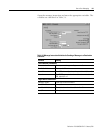
The procedure to send configuration data (nodes 100 to 149), or data
(nodes 0 to 49) is exactly the same as discussed previously in
“Configuring ENI Data Parameters” on page 4-6.
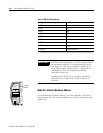
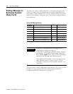
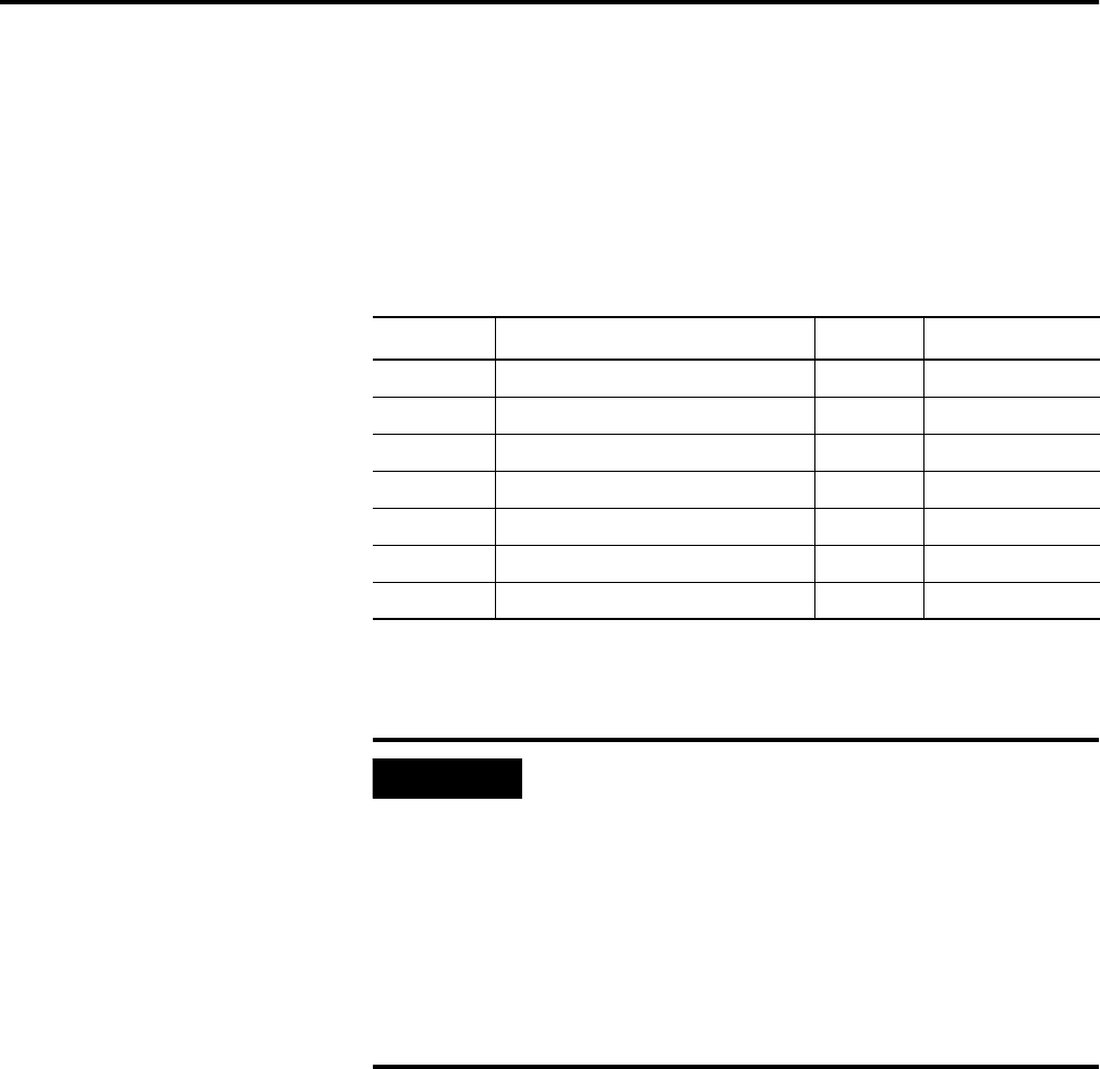
Table 5.3 DF1 Message Routing
ENI Node
(1)
(1) See IMPORTANT note below about assigning Nodes to various devices.
Function ENI Node Function
0 Route DF1 MSG to IP@address 100 100 Route 0 Address
1 Route DF1 MSG to IP@address 101 101 Route 1 Address
2 Route DF1 MSG to IP@address 102 102 Route 2 Address
3 Route DF1 MSG to IP@address 103 103 Route 3 Address
↓↓ ↓↓
48 Route DF1 MSG to IP@address 148 148 Route 48 Address
49 Route DF1 MSG to IP@address 149 149 Route 49 Address
IMPORTANT
In the ENI, node addresses 45 through 49 are
dedicated for sending messages to
1756-ENET/ControlLogix controllers. When sending
messages to a 1756-ENET/ControlLogix controller,
the controller MUST be in slot 0 of the ControlLogix
chassis for the message to be delivered to it.
Node addresses 0 through 44 are to be used for all
other Ethernet devices, such as other 1769-L20
controllers connected to ENI modules and SLC 5/05
controllers.