


Publication 1761-UM006A-EN-P - February 2001
Peer-to-Peer Messaging 5-3
Message to Configuration
Nodes (Nodes 100 to 149)
When the ENI receives a message to Node Address 0 to 49, it looks up
the TCP/IP address associated with the address at Nodes 100 to 149.
The ENI preserves the original DF1 address when sending back a
reply.
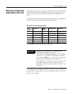
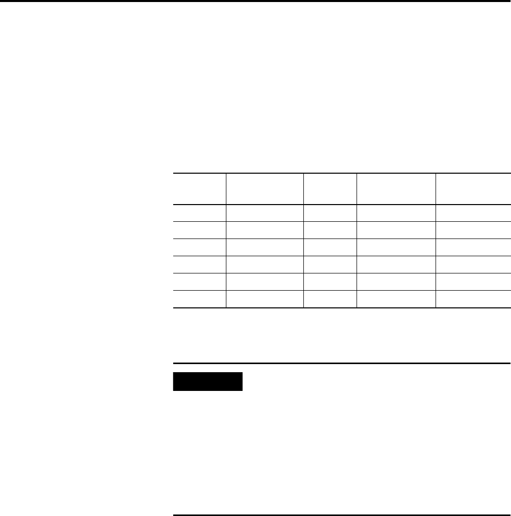
The following table illustrates the relationship between configuration
addresses and their corresponding messaging address.
To configure the route address (nodes 100 to 149), write a 485CIF
message with 4 integer data words. An example is shown in the next
section of this chapter.
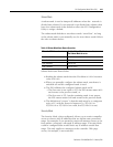
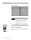
Table 5.2 Peer-to-Peer Message Routing
Node
Number
(1)
(1) See IMPORTANT note below about assigning Nodes to various devices.
Function Node
Number
Routing Table Data Type
0 DF1 Route 0 MSG 100 Route 0 Address Integer (4 words)
1 DF1 Route 1 MSG 101 Route 1 Address Integer (4 words)
2 DF1 Route 2 MSG 102 Route 2 Address Integer (4 words)
3 DF1 Route 3 MSG 103 Route 3 Address Integer (4 words)
↓↓ ↓↓ ↓
49 DF1 Route 49 MSG 149 Route 149 Address Integer (4 words)
IMPORTANT
In the ENI, node addresses 45 through 49 are
dedicated for sending messages to
1756-ENET/ControlLogix controllers. When sending
messages to a 1756-ENET/ControlLogix controller,
the controller MUST be in slot 0 of the ControlLogix
chassis for the message to be delivered to it.
Node addresses 0 through 44 are to be used for all
other Ethernet devices, such as other 1769-L20
controllers connected to ENI modules and SLC 5/05
controllers.