


Publication 1761-UM006A-EN-P - February 2001
7-8 Connecting 1769-L20 CompactLogix Controllers on Ethernet
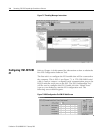
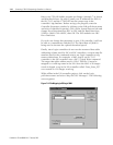
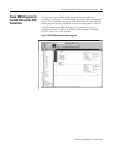
The 5 rungs used to configure ENI #2 are defined as follows:
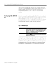
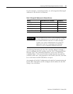
The following table contains the information needed to send
messages to the ENI to configure it for this example. For a complete
list of ENI configurable features, please refer to Chapters 4 and 5.
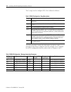
Table 7.3 ENI #2 Configuration - Rung Descriptions
Rung Function
Rung 2 This rung initiates the process and configures the ENI module’s Serial port for
38400 Baud.
Rung 3 This rung is initiated by the Done bit of the previous MSG and it disables
BOOTP.
Rung 4 This rung configures the ENI with its own IP address.
Rung 5 This rung adds the IP address of the SLC 5/05 controller to the ENI module’s
Message Routing table at DF1 node 1. This means that any message sent by
the -L20 controller with a DF1 destination address of 1, will be sent to the SLC
5/05 controller on Ethernet.
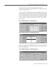
Rung 6 This rung adds the IP address of the 1756-ENET module to the ENI module’s
Message Routing table at DF1 node 45. This means that any message sent by
the -L20 controller with a DF1 destination address of 45, will be sent to the
5550 controller in slot 0, via the 1756-ENET module on Ethernet.
Rung 7 This rung instructs the ENI module to save the configuration data sent to it in
non-volatile memory.
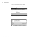
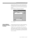
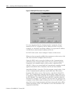
Table 7.4 ENI #2 Configuration - Message Instructions Parameters
Configuration
Node Number
Configuration Function Data Type Message Node
Number
Message
Length (bytes)
Message Function
101 Configure Route 1 Address Integers 1 8 Route DF1 MSG to IP at Address 1
145 Configure Route 45 Address Integers 45 8 Route DF1 MSG to IP at Address 2
248 Save/Reset Integer N/A 2 0 = save configuration to flash
250 TCP/IP Config. Integer N/A 8 Assign an IP Address to the ENI
252 BOOTP Integer N/A 2 1 = disable BOOTP
253 Baud Rate Integer N/A 2 6 = 38400 Baud