


HP OmniBook 2100/3000/3100 Removal and Replacement 2-29
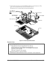
Reassembly Notes
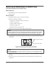
Caution
Align the IC with the slot in the socket. The IC is keyed to fit correctly. If you insert the IC
backward, the IC or motherboard could be damaged.
• Press down firmly on the IC with your thumb to ensure a proper connection.
• Reprogram the IC by programming the BIOS—see the note above.
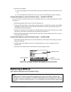
Removing Other Components
(HP Authorized Service Providers Only)
Required Equipment
• Small Phillips screwdriver.
• Pointed knife or probe (for display components).
• 5-mm hex driver (for bottom case components).
Removal Procedure
1. Unplug the ac adapter, if present, and remove the battery.
2. Remove the additional assemblies and follow the special steps indicated in the tables below.
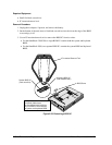
Table 2-8. Removing Other Components (Authorized Providers)
Component Removal Procedures Additional Steps
Bracket, Display
See pages 2-15 and 2-17.
Cable, Icon/MB
Plug-in module (page 2-4).
Display, but only until the
icon PCA is removed
(page 2-8).
The display does not have to be removed.
Cable, Inverter/MB
(12-inch display)
Plug-in module (page 2-4).
Display (page 2-8).
LCD module, but only until
the bezel is removed (page
2-11).
Reassembly Notes: The cable should protrude about
6 cm from the hinge.
Caution: Use compatible parts (page 2-11).
Cable, Inverter/MB
(13-inch display)
Plug-in module (page 2-4).
Display (page 2-8).
LCD module (page 2-11).
Display case (page 2-17).
Reassembly Notes: The cable should protrude about
6 cm from the hinge.
Secure the inverter/MB cable to the case near the
hinge area with a piece of Kapton tape.
Caution: Use compatible parts (page 2-11).
Cable, IR/Icon
Plug-in module (page 2-4).
Hard drive (page 2-5).
Display (page 2-8).
Keyboard (page 2-19).
Top case (page 2-20).
Remove the screws from the IR PCA and the speaker
bracket.
Reassembly Notes: Make sure the cable is clamped
by the bracket, and it routes through the bottom corner
of the window opening.