


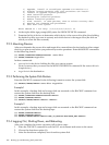
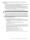

10. When you next see the boot option list displayed at your console by EFI, it should look
similar to the following (assuming you took the default in step 7). In this example, the device
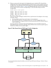
is $1$DGA1 for two dual-ported EVA5000 storage arrays (the four separate boot paths are
identified in the display). Figure E-1 (page 299) illustrates the host FC ports (FGA0 and FGB0)
on the Integrity servers and the corresponding FC SAN/EVA5000 storage controller
configuration.
Please select a boot option
$1$dga1 FGA0.5000-1FE1-0011-B15C
$1$dga1 FGA0.5000-1FE1-0011-B158
$1$dga1 FGB0.5000-1FE1-0011-B15D
$1$dga1 FGB0.5000-1FE1-0011-B159
EFI Shell [Built-in]
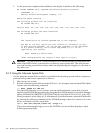
The text to the right of $1$dga1 identifies the boot path from the host adapter to the storage
controller, where:
• FGA0 or FGB0 are the FC ports (also known as host adapters).
• Each 5000-1FE1-0011-B15 n number (where n is C, 8, D, or 9, respectively) is the
factory-assigned FC storage port 64-bit worldwide identifier (WWID), otherwise known
as the FC port name.
If you get confused, simply boot the OpenVMS Integrity servers OE DVD and use the
OpenVMS Integrity servers Boot Manager utility to remove the current boot options (option
3) and then to add your boot options again.
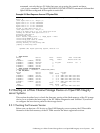
Figure E-1 Fibre Channel Host and SAN Storage Controller Configuration
Integrity Server running
OpenVMS
5000-1FE1-0011-B1595000-1FE1-0011-B158 5000-1FE1-0011-B15D5000-1FE1-0011-B15C
FGB0FGA0
FC SAN
EVA5000 Storage Controller
FC SAN
System Disk
For more information about this utility, see the HP OpenVMS System Manager's Manual, Volume
1: Essentials.
E.2 Booting on a Fibre Channel Storage Device on OpenVMS Integrity server Systems 299