


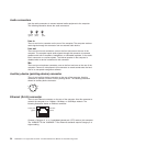

The Ethernet connector has one LED that indicates Ethernet-link status. When this
LED is lit, it indicates that there is an active connection on the Ethernet port. Activity
between the computer and the network is indicated by the Ethernet transmit/receive
activity LEDs on the front and rear of the computer (see “Controls, LEDs, and
connectors” on page 6).
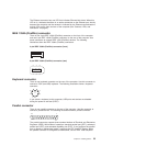
IEEE 1394A (FireWire) connector
There is one 4-pin IEEE 1394A (FireWire) connector on the front of the computer
and one 6-pin IEEE 1394A (FireWire) connector on the rear of the computer. Use
these connectors to connect IEEE 1394 (FireWire) devices. The following
illustrations show the IEEE 1394A (FireWire) connectors.
4-pin IEEE 1394A (FireWire) connector (front)
4
3
21
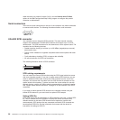
6-pin IEEE 1394A (FireWire) connector (rear)
1
2
3
4
5
6
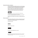
Keyboard connector
There is one keyboard connector on the rear of the computer. Use this connector to
connect a PS/2 (non-USB) keyboard. The following illustration shows a keyboard
connector.
6
4
2
1
3
5
If you attach a keyboard to this connector, USB ports and devices are disabled
during the power-on self-test (POST).
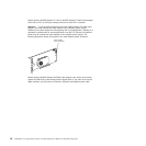
Parallel connector
There is one parallel connector on the rear of the computer. Use this connector to
connect a parallel device. The following illustration shows a parallel connector.
13
1
25
14
The parallel connector supports three standard Institute of Electrical and Electronics
Engineers (IEEE) 1284 modes of operation: standard parallel port (SPP), enhanced
parallel port (EPP), and extended capability port (ECP). If you configure the parallel
port to operate in bidirectional mode, it supports the ECP and EPP modes. When
the parallel connector is configured as bidirectional, use an IEEE 1284-compliant
Chapter 4. Installing options 55