


1-11
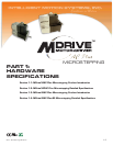
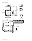
Part 1: Hardware Specifications
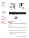
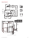
P1 19-Pin M23 Connector - I/O, SPI Communications with Encoder Interface
Option
Pin Assignment - P1 I/O, SPI and Encoder
Connections
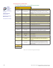
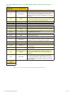
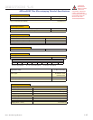
Pin # Function Description
Pin 1 Opto Reference
The signal applied to the Optocoupler Reference will
determine the sinking/ or sourcing configuration of the inputs.
To set the inputs for sinking operation, a +5 to +24 VDC
supply is connected. If sourcing, the Reference is connected
to Ground.
Pin 2 Enable
Enable/Disable Input will enable or disable the driver output
to the motor. In the disconnected state the driver outputs are
enabled in either sinking or sourcing configuration.
Pin 3 Index + Encoder Index + Output.
Pin 4 Channel B + Encoder Channel B + Output.
Pin 5 Channel B – Encoder Channel B – Output.
Pin 6 N/C No Connect.
Pin 7 Channel A + Encoder Channel A + Output.
Pin 8 MOSI Master-Out/Slave-In. Carries output data from the SPI Master
Pin 9 CS
SPI Chip Select. This signal is used to turn communications
on multiple MDM units on or off.
Pin 10 +5 VDC Output Supply voltage for the MD-CC300-000 Cable ONLY!
Pin 11 GND Communications Ground.
Pin 12 N/C No Connect.
Pin 13
Direction/Channel B/
Clock Down
Direction input. The axis direction will be with respect to the
state of the Direction Override Parameter. It may also receive
quadrature and clock up type inputs if so configured.
Pin 14 Index – Encoder Index – Output.
Pin 15 Channel A – Encoder Channel A – Output.
Pin 16 SPI Clock
The Clock is driven by the SPI Master. The clock cycles once
for each data bit.
Pin 17 MISO
Master-In/Slave-Out. Carries output data from the MDM back
to the SPI Master.
Pin 18
Step Clock/Channel A/
Clock Up
Step Clock input. The step clock input will receive the clock
pulses which will step the motor 1 step for each pulse. It
may also receive quadrature and clock up type inputs if so
configured.
Pin 19
Fault Output
Open-Drain pending Over-temperature and Over-temperature
Fault. When device reaches the temperature specified by
the warning temperature the output will pulse at 1 second
intervals. When in Over-temperature fault the output will be
active continually.
Recommended
Cordset
MD-CS100-000 or
MD-CS101-000
Table 1.2.3: P1- 19-Pin M23 Pin Assignment and Description (Internal Optical Encoder)