


The information in this book has been carefully checked and is believed to be accurate; however, no responsibility is assumed for
inaccuracies.
Intelligent Motion Systems, Inc., reserves the right to make changes without further notice to any products herein to improve reliability,
function or design. Intelligent Motion Systems, Inc., does not assume any liability arising out of the application or use of any product or
circuit described herein; neither does it convey any license under its patent rights of others. Intelligent Motion Systems and are
trademarks of Intelligent Motion Systems, Inc.
Intelligent Motion Systems, Inc.’s general policy does not recommend the use of its products in life support or aircraft applications
wherein a failure or malfunction of the product may directly threaten life or injury. Per Intelligent Motion Systems, Inc.’s terms and
conditions of sales, the user of Intelligent Motion Systems, Inc., products in life support or aircraft applications assumes all risks of such
use and indemnifies Intelligent Motion Systems, Inc., against all damages.
TM
MDriveAC Plus Microstepping
Revision R121707
Copyright © Intelligent Motion Systems, Inc.
All Rights Reserved
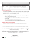
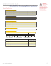
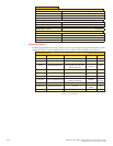
MDriveAC Plus Motion Control Hardware Reference Change Log
Date Revision Changes
03/07/2006 R030706 Initial Release
04/13/2006 R041306 Corrected Motor+Driver weight specification for MDM34AC Plus, added notes on recommended mating connector for
the M23 19-pin connector P1. Added MD-CS10x-000 and MD-CS-20x-000 To Appendix C.
05/04/2006 R050406 Removed Ambient Temperature Specification
05/25/2006 R052506 Replaced USB to SPI Cable Driver Installation with instructions relavent to Windows XP Service Pack 2.
03/02/2007 R030207 Reworked IMS SPI Motor Interface Section, added information relevant to UL recognition. Added Enable Active High/
Low parameter for SPI, changed temperature specification to: -40°C to +75°C (non-condensing humidity), measured at
the heat sink, and -40°C to +90°C (non-condensing humidity), measured on the motor.
12/17/2007 R121707 Minor updates and corrections. Made relevant to Firmware Version 3.0.02. Added Appendix for size 34 Linear slide.
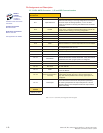
Low Voltage Installation Information
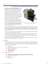
Certain practices must be followed when installing the AC motor drives in order to meet the requirements of the Low Voltage Directive 73/23/EEC
and as amended by Directive 93/68/EEC. The AC motor drives are components intended for installation within other electrical systems or ma-
chines. The system or machine builder must ensure their product complies with the applicable standards required for that equipment. The following
information applies to the AC motor drives as far as the Low Voltage Directive is concerned.
1) The AC motor drives are designed to be installed in a pollution degree level 2 environment.
2) All control inputs and outputs are isolated from AC power with a basic insulation rating. The minimum clearance and creepage distance
on the printed wiring board from the AC input to the control inputs and outputs is 3 millimeters. This is representative of an impulse
rating of 4 KV (1.2/50 us) as referenced in standard EN50178.
3) The control inputs and outputs may require an additional level of protection against direct contact if such protection is required by the
standards governing the overall system or machine and its intended environment. It is the machine builder’s responsibility to provide
this protection if needed.
4) Be sure to wire the AC power and earth ground connection as shown in the operator’s manual.
5) All cautions and warnings listed throughout the operator’s manual must be followed to insure safe system operation.
UL Application Details and Conditions of Acceptance
The UL Application Details and Conditions of Acceptance are located on the wed at http://www.imshome.com/CE_conformity.html.