


i
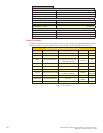
Table Of Contents
Getting Started: MDriveAC Plus Microstepping ..........................................................................1-1
Before You Begin ....................................................................................................................... 1-1
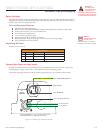
Connecting AC Power ............................................................................................................... 1-1
Connect Opto Power and Logic Inputs ..................................................................................... 1-1
Connecting Parameter Setup Cable ...........................................................................................1-2
Install the IMS SPI Motor Interface .......................................................................................... 1-2
Part 1: Hardware Specifications
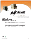
Section 1.1: Introduction to the MDrive34AC Plus Microstepping ..............................................1-5
Configuring .............................................................................................................................. 1-5
Features and Benefits ................................................................................................................. 1-5
Section 1.2: MDrive34AC Plus Microstepping Detailed Specifications ........................................1-7
General Specifications ............................................................................................................... 1-7
Setup Parameters ....................................................................................................................... 1-8
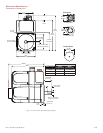
Mechanical Specifications ..........................................................................................................1-9
Pin Assignment and Description ............................................................................................. 1-10
P1 19-Pin M23 Connector - I/O and SPI Communications ......................................... 1-10
P1 19-Pin M23 Connector - I/O, SPI Communications with Encoder Interface Option 1-11
P3 Connector - AC Power ............................................................................................. 1-12
Internal Encoder ...........................................................................................................1-12
Control Knob ............................................................................................................... 1-12
Planetary Gearbox .........................................................................................................1-12
Parameter Setup Cable and Adapter ..............................................................................1-12
Cordsets ........................................................................................................................ 1-12
Section 1.3: Introduction to the MDrive42AC Plus Microstepping ............................................1-13
Configuring ............................................................................................................................ 1-13
Features and Benefits ............................................................................................................... 1-13
Section 1.4: MDrive42AC Plus Microstepping Detailed Specifications ......................................1-15
Setup Parameters ..................................................................................................................... 1-16
Pin Assignment and Description ............................................................................................. 1-18
P1 19-Pin M23 Connector - I/O and SPI Communications ......................................... 1-18
P1 19-Pin M23 Connector - I/O, SPI Communications with Encoder Interface Option 1-19
P3 Connector - AC Power ............................................................................................. 1-20
Internal Encoder ...........................................................................................................1-21
Control Knob ............................................................................................................... 1-21
Parameter Setup Cable and Adapter ..............................................................................1-21
Cordsets ........................................................................................................................ 1-21
Part 2: Interfacing and Configuration
Section 2.1: Logic Interface and Connection ...............................................................................2-3
Optically Isolated Logic Inputs ..................................................................................................2-3
Isolated Logic Input Pins and Connections ............................................................................... 2-3
Isolated Logic Input Characteristics ........................................................................................... 2-4
Enable Input ................................................................................................................... 2-4
Clock Inputs ................................................................................................................... 2-4
Optocoupler Reference .............................................................................................................. 2-6
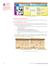
Input Connection Examples ...................................................................................................... 2-7
Open Collector Interface Example .................................................................................. 2-7
Switch Interface Example ................................................................................................ 2-8
Fault Output ............................................................................................................................. 2-8
Minimum Required Connections .............................................................................................. 2-9
Section 2.2: Connecting SPI Communications ..........................................................................2-10
Connecting the SPI Interface .................................................................................................. 2-10
SPI Signal Overview ................................................................................................................ 2-10
SPI Pins and Connections ....................................................................................................... 2-11
SPI Master with Multiple MDriveAC Plus Microstepping ...................................................... 2-11