


A-21
Appendices
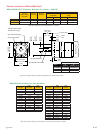
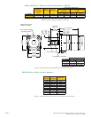
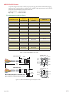
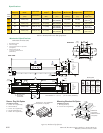
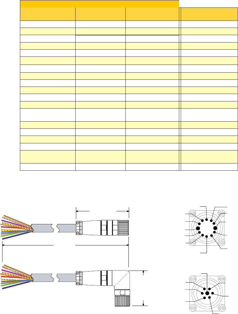
Table C.1: MD-CS10x-000 Wire Color Chart
Pin Assignment and Wire Colors
P1 - Expanded I/O Configuration
Cordset Wire Color
Function
(Expanded I/O)
Function (Optical
Encoder)
MDrive P1
Violet Opto Reference Opto Reference Pin 1
Red Enable Enable Pin 2
Grey N/C Index + Pin 3
Red/Blue N/C Channel B + Pin 4
Green N/C Channel B – Pin 5
Blue N/C N/C Pin 6
Gray/Pink N/C Channel A + Pin 7
White/Green MOSI MOSI Pin 8
White/Yellow CS CS Pin 9
White/Gray +5 VDC Output +5 VDC Output Pin 10
Black GND GND Pin 11
Green/Yellow N/C N/C Pin 12
Yellow/Brown
Direction/Channel
B/ Clock Down
Direction/Channel B/
Clock Down
Pin 13
Brown/Green N/C Index – Pin 14
White N/C Channel A – Pin 15
Yellow SPI Clock SPI Clock Pin 16
Pink MISO MISO Pin 17
Gray/Brown
Step Clock/Channel
A/ Clock Up
Step Clock/Channel
A/ Clock Up
Pin 18
Brown
Fault Output Fault Output
Pin 19
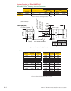
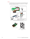
MD-CS100-000
MD-CS101-000
2.815”
(71.5 mm)
13.0’
(4.0 m)
2.37”
(60.2 mm)
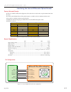
Pin 4
Pin 5
Pin 7
Pin 8
Pin 10
Pin 11
Pin 1
Pin 2
Pin 19
Pin 18
Pin 17
Pin 14
Pin 15
Pin 16
Outside: Pins 1 -12
Inside: Pins 13 - 19
Pin 3
Pin 12
Pin 6
Pin 9
Pin 13
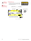
Ensure adequate space is available within
your enclosure for the cordset connector!
Figure C.13: MD-CS10x-000 Prototype Development Cordset
MD-CS10x-000 Cordset
19-pin M23 single-ended cordsets are offered to speed prototyping of the MDriveACPlus Microstepping.
Measuring 13.0' (4.0m) long, they are available in either straight or right angle termination. PVC jacketed
cables come with a foil shield and unconnected drain wire.
Straight Termination .....MD-CS100-000
Right Angle .................. MD-CS101-000