


1-1
Part 1: Hardware Specifications
WARNING!
The MDrive has
components which
are sensitive to
Electrostatic Discharge (ESD).
All handling should be done at
an ESD protected workstation.
Ge t t i n g S t ar t e d
MDriveAC Plus Microstepping
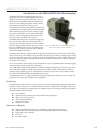
Before You Begin
The Quick Start guide is designed to help quickly connect and begin using your MDriveAC Plus Microstepping
integrated motor and driver. The following examples will help you get the motor turning for the first time and
introduce you to the basic settings of the drive.
Tools and Equipment Required
MDriveAC Plus Microstepping Unit.
Parameter setup cable MD-CC300-000 and Adapter MD-ADP-M23 or equivalent (USB to SPI).
Product CD or Internet access to www.imshome.com.
Control Device for Step/Direction.
+5 to +24 VDC optocoupler supply.
Basic Tools: Wire Cutters / Strippers / Screwdriver.
Wiring/Cabling for AC Power and Logic Connections (See Note in page margin).
A PC with Windows XP Service Pack 2.
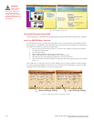
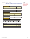
Connecting AC Power
AC Power to Connector P3.
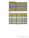
AC Power To P3
P3 Function US Color Euro Color
1 Earth GND Green Green/Yellow
2 AC Line Black Brown
3 AC Neutral White Blue
Table GS.1: AC Wire Colors
Connect Opto Power and Logic Inputs
Using the recommended wire (see the specifications for your MDriveAC Plus), connect the DC output of the
optocoupler power supply to the P1, Pin 1 of your MDriveAC Plus
Microstepping
model.
Connect the opto supply ground to the Power Ground pin appropriate for your controller/control circuitry.
Note: UL
Recognition requires
the use of the
MD-CS20x-000 or Lumberg
Equivalent AC Power Cordset.
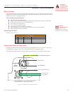
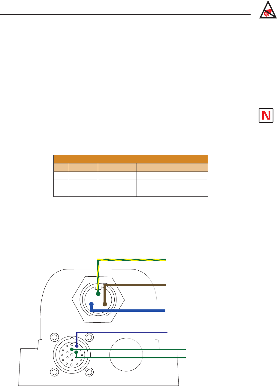
Figure GS.1: Minimum Logic and Power Connections
Pin 1: Optocoupler Reference*
Pin 1: Earth (Chassis) Ground
Pin 2: AC Line
Pin 3: AC Neutral
Pin 18: Step Clock
Pin 13: Direction
P3: AC Power
P1: I/O
{
MD-CS200-000
or
Lumberg
Equivalent
*Optocoupler Reference = +5 to +24 VDC: Sinking Inputs
*Optocoupler Reference = GND: Sourcing Inputs