


A-13
Appendices
Chain Drive
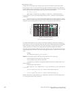
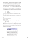
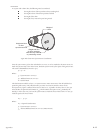
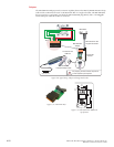
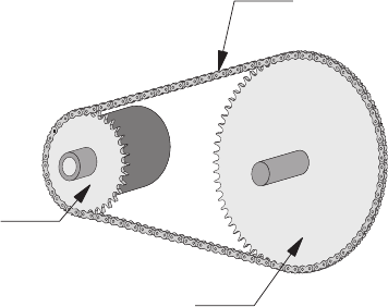
In a system with a chain drive, the following must be considered:
the weight and size of drive sprocket and any attaching hub
the weight and size of the driven sprocket and shaft
the weight of the chain
the weight of any material or parts being moved
Once the system inertia (J
L
) has been calculated in oz-in-sec
2
, it can be matched to the motor inertia. To
match the system inertia to the motor inertia, divide the system inertia by the square of the gearbox ratio.
The result is called Reflected Inertia or (J
ref
).
J
ref
= J
L
÷Ζ
2
Where:
J
L
= System Inertia in oz-in-sec
2
J
ref
= Reflected Inertia in oz-in-sec
2
Z = Gearbox Ratio
The ideal situation would be to have a 1:1 system inertia to motor inertia ratio. This will yield the best
positioning and accuracy. The reflected inertia (J
ref
) must not exceed 10 times the motor inertia.
Your system may require a reflected inertia ratio as close to 1:1 as possible. To achieve the 1:1 ratio, you
must calculate an Optimal Gearbox Ratio (Z
opt
) which would be the square root of J
L
divided by the
desired J
ref
. In this case since you want the system inertia to match the motor inertia with a 1:1 ratio, J
ref
would be equal to the motor inertia.
Z
opt
= J
L
÷ J
ref
Where:
Z
opt
= Optimal Gearbox Ratio
J
L
= System Inertia in oz-in-sec
2
J
ref
= Desired Reflected Inertia in oz-in-sec
2
(Motor Inertia)
Weight of
chain
Weight and size
of drive
sprocket and hub
Weight and size
of driven sprocket,
shaft and any material
or parts being moved
Figure B.6: Chain Drive System Inertia Considerations