


A-10
MDriveAC Plus Microstepping Hardware - Revision R121707
Relevant to Firmware Version 3.0.02
System Inertia
System inertia must be included in the selection of an MDrive and Planetary Gearbox. Inertia is the resistance
an object has relative to changes in velocity. Inertia must be calculated and matched to the motor inertia. The
Planetary Gearbox ratio plays an important role in matching system inertia to motor inertia. There are many
variable factors that affect the inertia. Some of these factors are:
The type of system being driven.
Weight and frictional forces of that system.
The load the system is moving or carrying.
The ratio of the system inertia to motor inertia should be between 1:1 and 10:1. With 1:1 being ideal, a 1:1 to
5:1 ratio is good while a ratio greater than 5:1 and up to 10:1 is the maximum.
Type of System
There are many systems and drives, from simple to complex, which react differently and possess varied
amounts of inertia. All of the moving components of a given system will have some inertia factor which
must be included in the total inertia calculation. Some of these systems include:
Lead screw
Rack and pinion
Conveyor belt
Rotary table
Belt drive
Chain drive
Not only must the inertia of the system be calculated, but also any load that it may be moving or carrying.
The examples below illustrate some of the factors that must be considered when calculating the inertia of a
system.
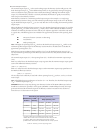
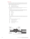
Lead Screw
In a system with a lead screw, the following must be considered:
The weight and preload of the screw
The weight of the lead screw nut
The weight of a table or slide
The friction caused by the table guideways
The weight of any parts
Preload on
leadscrew
Weight of
table
Weight of
parts
Friction of
guideways
Weight of
nut
Weight of
screw
Figure B.2: Lead Screw System Inertia Considerations