


2-11
Part 2: Interfacing and Configuring
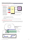
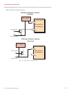
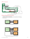
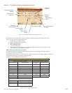
SPI Master
SPI Clock
MOSI
MISO
CS
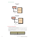
SPI Clock
MOSI
MISO
CS1
CS2
SPI Master
MDriveACPlus
Microstepping
#1
MDriveACPlus
Microstepping
MDriveACPlus
Microstepping
#2
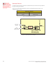
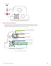
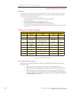
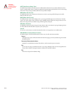
SPI Pins and Connections
Figure 2.2.2: SPI Pins and Connections, 10-Pin IDC
P1: I/O
COMM GND
+5 VDC OUT
CHIP SELECT
MASTER IN/SLAVE OUT
SPI CLOCK
MASTER OUT/SLAVE IN
19
15
2 3 4
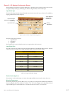
PC Parallel/SPI Port
For Use ONLY
with IMS Parameter
Setup Cable
Figure 2.2.4: SPI Master with a Single MDriveAC Plus Microstepping
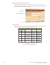
SPI Master with Multiple MDriveAC Plus Microstepping
It is possible to link multiple MDriveAC Plus Microstepping units in an array from a single SPI Master by wiring the system and
programming the user interface to write to multiple chip selects.
Each MDriveAC Plus on the bus will have a dedicated chip select. Only one system MDriveAC Plus can be communicated with/
Parameters changed at a time.
Figure 2.2.5: SPI Master with Multiple MDriveAC Plus Microsteppings