


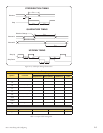
2-9
Part 2: Interfacing and Configuring
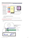
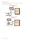
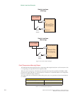
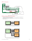
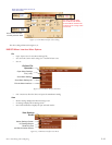
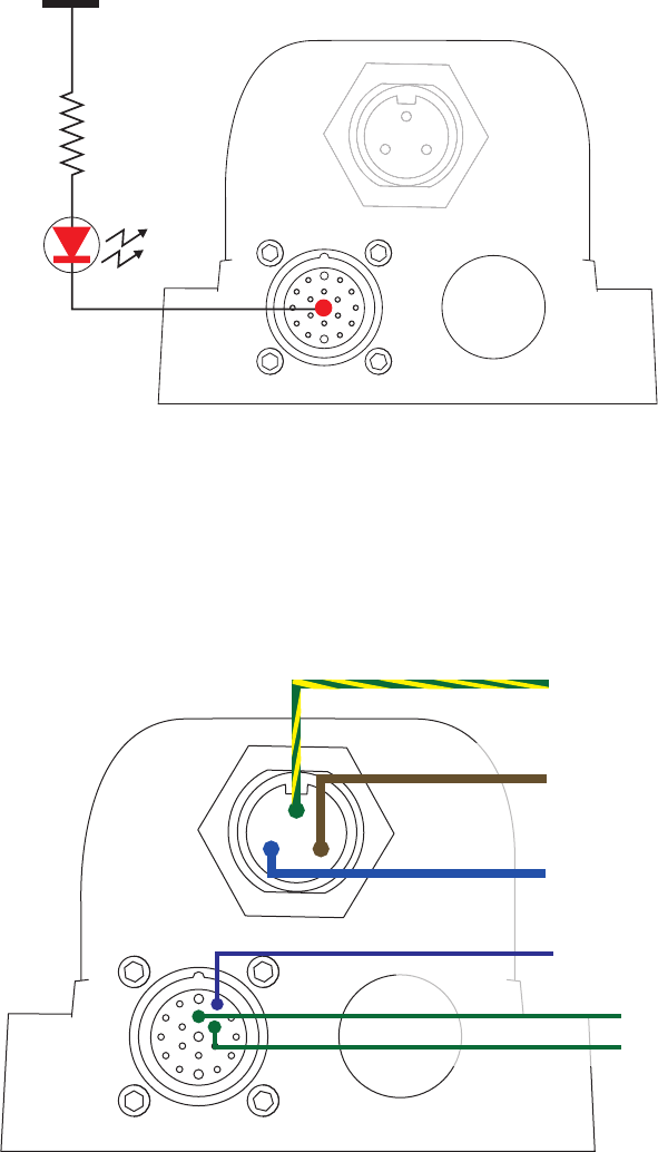
Minimum Required Connections
The connections shown are the minimum required to operate the MDriveAC Plus Microstepping. These are illus-
trated in both Sinking and Sourcing Configurations. Please reference the Pin Configuration diagram and Specifica-
tion Tables for the MDriveAC Plus Microstepping connector option you are using.
Figure 2.1.8 Minimum Required Connections
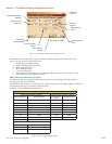
Pin 1: Optocoupler Reference*
Pin 1: Earth (Chassis) Ground
Pin 2: AC Line
Pin 3: AC Neutral
Pin 18: Step Clock
Pin 13: Direction
P3: AC Power
P1: I/O
{
MD-CS200-000
or
Lumberg
Equivalent
*Optocoupler Reference = +5 to +24 VDC: Sinking Inputs
*Optocoupler Reference = GND: Sourcing Inputs
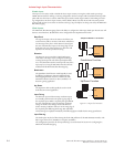
+5 to +24 VDC
Current Limiting
Resistor
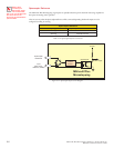
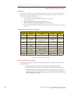
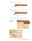
P1: Pin 19 - Fault Output
P1: Pin 11 - Comm Ground
P1: I/O
LED
Pin 19
Figure 2.1.7: Fault Output interfaced to an LED