


A-23
Appendices
Ap p e n d i x D
Interfacing the Internal Differential Optical Encoder
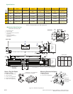
Factory Mounted Encoder
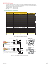
Encoders are available in differential configurations. All encoders have an index mark, except the MDrive42AC 400
line count.
Use of the encoder feedback feature of this product requires a controller such as an IMS MicroLYNX or PLC.
The encoder has a 100 kHz maximum output frequency.
The MDriveAC Plus Microstepping are available with an internal differential optical encoder.
Available line counts are:
MDrive34AC MDrive42AC
Line Count Part Number Line Count Part Number
100 EA 100 EA
200 EB 200 EB
250 EC —— ——
256 EW —— ——
400 ED 400 ED
500 EH 500 EH
512 EX 512 EX
1000 EJ 1000 EJ
1024 EY 1024 EY
Table D1: Available Encoder Line Counts and Part Numbers
General Specifications
Min Typ Max Units
Supply Voltage (VDC) ......................... -0.5 ........................................................... 7 ......................Volts
Supply Current ......................................30............................. 57 ..........................85 ..................... mA
Output Voltage .................................... -0.5 ......................................................... Vcc ...................Volts
Output Current (Per Channel) ............. -1.0 ........................................................... 5 ....................... mA
Maximum Frequency ................................................................................................................. 100kHz
Inertia ...............................................................................................0.565 g-cm
2
(8.0 x 10
-6
oz-in-sec
2
)
Temperature
Operating ................................................................................................................ -40 to +100° C
Storage ..................................................................................................................... -40 to +100° C
Humidity ............................................................................................................ 90% (non-condensing)
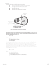
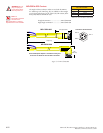
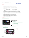
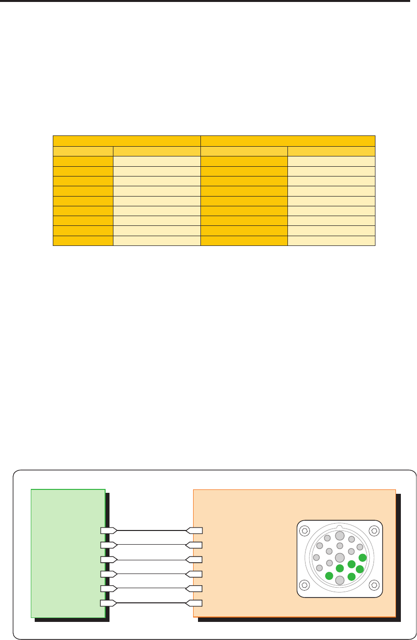
Pin Configuration
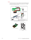
Figure D.1: Internal Differential Encoder Pin Configuration
Pin 3: Index +
P1
Pin 4: Channel B +
Pin 5: Channel B -
Pin 7: Channel A +
Pin 15: Channel A -
Pin 14: Index -
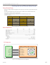
MDriveAC Plus Microstepping
Controller
Index -
Index +
Channel A+
Channel B -
Channel B +
Channel A -
12
6
3
9
1
2
4
5
7
8
10
11
15
19
18
13
14
17
16