


A-24
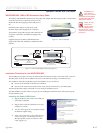
MDriveAC Plus Microstepping Hardware - Revision R121707
Relevant to Firmware Version 3.0.02
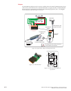
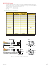
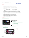
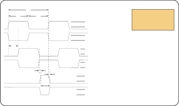
C
t1
t2
Po
X
Y
Z
2.4 V
0.4 V
2.4 V
0.4 V
2.4 V
0.4 V
2.4 V
0.4 V
2.4 V
0.4 V
2.4 V
0.4 V
Channel
A
+
Channel B +
Index +
Channel
A
-
Channel B -
Index -
Rotation:
CW – B Leads A
CCW – A Leads B
(C) One Cycle: 360 electrical degrees (°e)
(X/Y) Symmetry: A measure of the relationship between X and Y, nominally 180°e.
(Z) Quadrature: The phase lag or lead between channels A and B, nominally 90°e.
(Po) Index Pulse Width: Nominally 90°e.
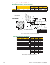
Encoder Signals
Differential Encoder
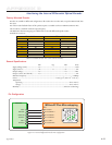
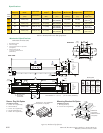
Cha racte risti cs
Parameter Symbol Min Typ Max Units
Cycle Error ................................................................................................3 .................... 5.5 .................°e
Symmetry ............................................................................. 130 ............ 180 ..................230 ................°e
Quadrature ............................................................................ 40 .............. 90 ...................140 ................°e
Index Pulse Width ..............................................Po .............. 60 .............. 90 ...................120 ................°e
Index Rise After CH B or CH A fall ................... t1 ..............-300 ........... 100 ..................250 ................ns
Index Fall After CH A or CH B rise ................... t2 ............... 70 ............. 150 .................1000 ...............ns
Over recommended operating range. Values are for worst error over a full rotation.
Figure D.2: Differential Encoder Signal Timing
Note: Rotation is as viewed from the cover side.