


2-17
Part 2: Interfacing and Configuring
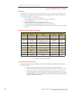
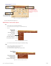
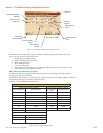
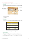
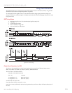
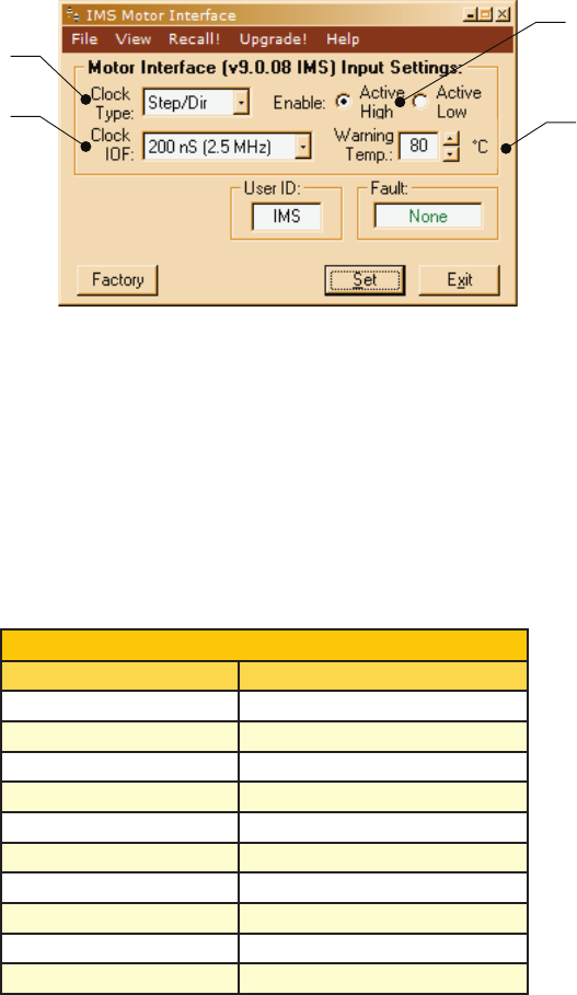
Screen 2: I/O Settings Configuration Screen
The I/O Settings screen may be accessed by clicking View > IO Settings on the menu bar. This screen is used to
configure the Input Clock type, the filtering and the Active High/Low State of the Enable Input.
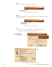
Input Clock Type
The Input Clock Type translates the specified pulse source that the motor will use as a reference for establishing
stepping resolution based on the frequency.
The three clock types supported are:
1. Step/Direction
2. Quadrature
3. Up/Down
The Clock types are covered in detail in Section 2.2: Logic Interface and Connection.
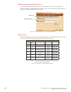
Input Clock Filter
The clock inputs may also be filtered using the Clock IOF pull down of the IMS SPI Motor Interface. The filter
range is from 50 nS (10 MHz) to 12.9 µSec. (38.8 kHz). Table 2.4.3 shows the filter settings.
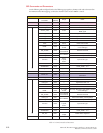
Input Clock Filter Settings
Min Pulse Cutoff Frequency
50 nS 10 MHz
150 nS 3.3 MHz
200 nS 2.5 MHz
300 nS 1.67 MHz
500 nS 1.0 MHz
900 nS 555 kHz
1.7 µS 294.1 kHz
3.3 µS 151 kHz
6.5 µS 76.9 kHz
12.9 µS 38.8 kHz
Table 2.3.4: Input Clock Filter Settings
Enable Active High/Low
The parameter sets the Enable Input to be Active when High (Default, Disconnected) or Active when Low.
Warning Temperature
The Warning Temperature parameter allows you to set a pending over-temperature threshold for the MDriveAC
Plus Microstepping. When that threshold is reached, a "TW" error code will appear in the Fault field. The Fault
output will also begin to activate/deactivate at 1 second intervals (1/2 second on, 1/2 second off).
Input Clock Type
(Step/Dir, Quadrature or
Up/Down)
Input Clock Filter
Active High/Low
State of the
Enable Input
Warning
Temperature
Figure 2.3.8: SPI Motor Interface I/O Settings Screen