


Design and Environmental Specifications Intel® Server Boards S5000PSL and S5000XSL TPS
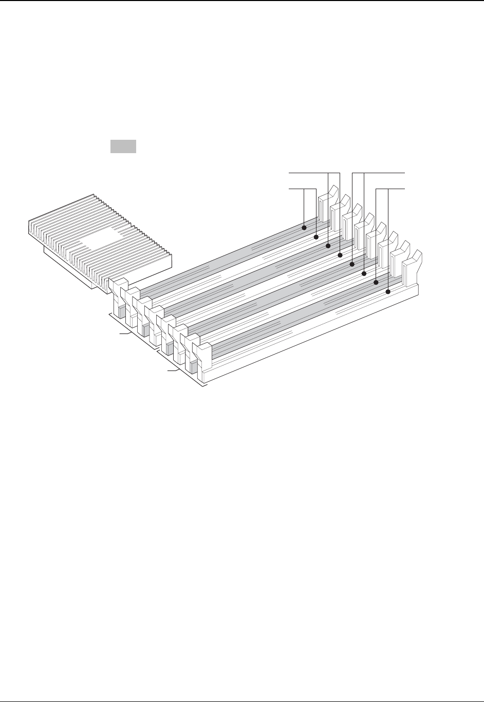
3.1.3.4 Non-mirrored Mode Memory Upgrades
The minimum memory upgrade increment is two DIMMs per branch. The DIMMs must cover the
same slot position on both channels. DIMMs pairs must be identical with respect to size, speed,
and organization. DIMMs that cover adjacent slot positions do not need to be identical.
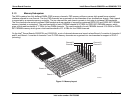
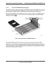
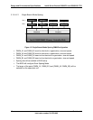
When adding two DIMMs to the configuration shown in
Figure 13 (above), the DIMMs should be
populated in DIMM sockets C1 and D1 as shown in the following diagram. Populated DIMM
sockets are shown in Grey.
TP02301
DIMM D2
DIMM D1
DIMM C2
DIMM C1
DIMM B2
DIMM B1
DIMM A2
DIMM A1
Branch 0
MCH
Channel A
Channel B
Channel D
Channel C
Branch 1
Figure 14. Recommended Four DIMM Configuration
Functionally, DIMM sockets A2 and B2 could also have been populated instead of DIMM
sockets C1 and D1. However, your system will not achieve equivalent performance.
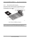
Figure 13,
on the previous page, shows the supported DIMM configuration that is recommended because it
allows both branches to operate independently and simultaneously. FBD bandwidth is doubled
when both branches operate in parallel.
Revision 1.2
Intel order number: D41763-003
38