


Design and Environmental Specifications Intel® Server Boards S5000PSL and S5000XSL TPS
Revision 1.2
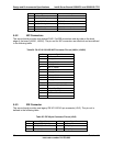
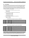
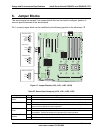
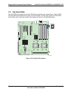
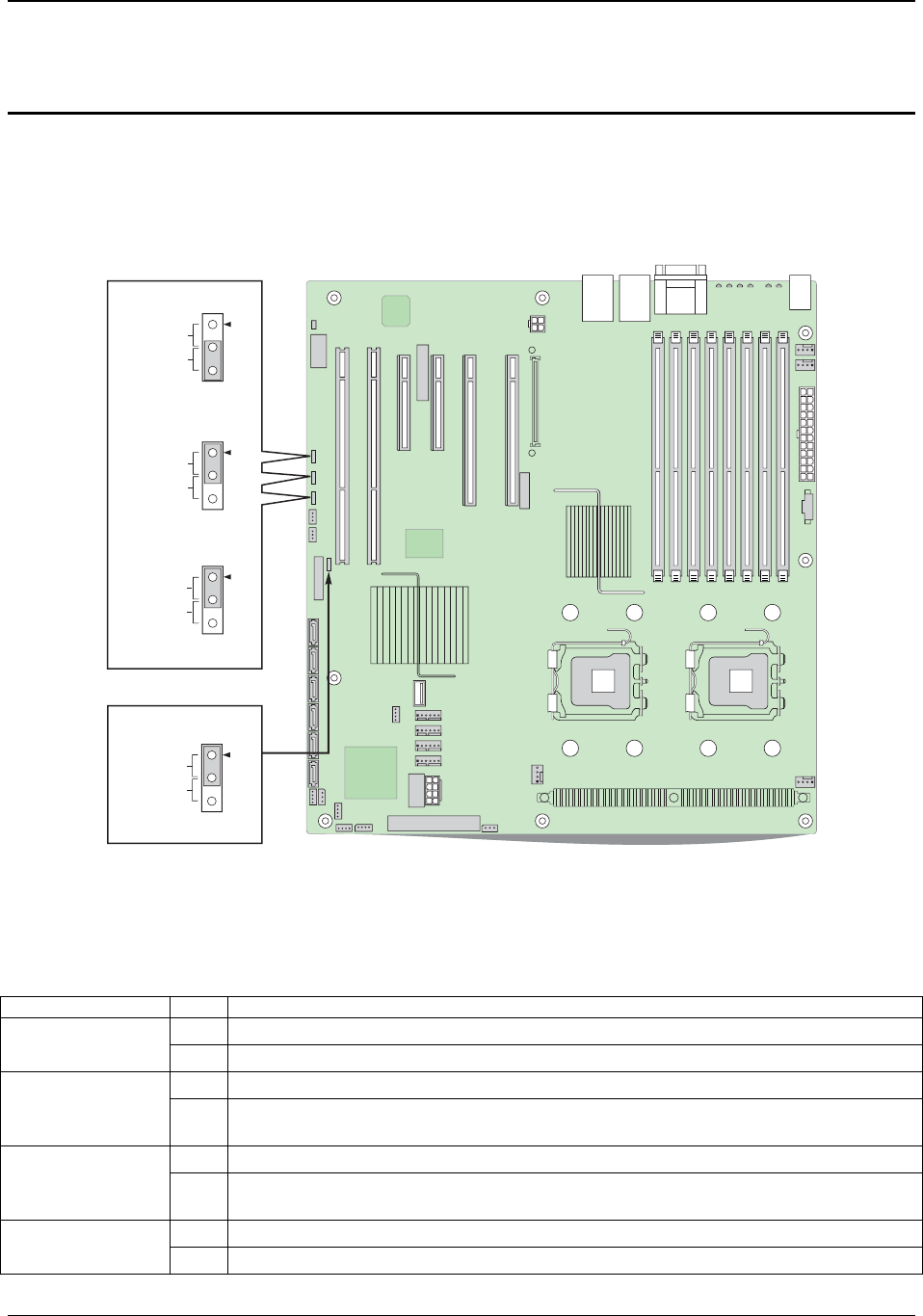
6. Jumper Blocks
The server board has several 3-pin jumper blocks that can be used to configure, protect, or
recover specific features of the server board.
Pin 1 on each jumper block can be identified by the following symbol on the silkscreen: ▼
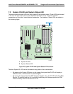
AF000422
3
2
CMOS Clear
3
2
Password Clear
J1E3
J1D1
Disable
Enable
3
2
BMC Force Update
J1D2
Disable
Enable
BIOS Bank Select
J1C3
3
2
Force Lower
Bank
Normal
Operation
(default)
Protect
Clear
Figure 17. Jumper Blocks (J1C3, J1D1, J1D2, J1E32)
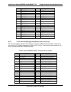
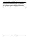
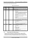
Table 35. Server Board Jumpers (J1C3, J1D1, J1D2, J1E3)
Jumper Name Pins System Results
1-2
Intel order number: D41763-003
68
If these pins are jumper the system will boot from an alternate BIOS image. J1C3: BIOS Bank
Select
2-3
System is configured for normal operation. (Default)
1-2
These pins should have a jumper in place for normal system operation. (Default)
J1D1: CMOS Clear
2-3 If these pins are jumpered, the CMOS settings will be cleared immediately. These pins
should not be jumpered for normal operation
1-2
These pins should have a jumper in place for normal system operation. (Default)
J1D2: Password
Clear
2-3 If these pins are jumpered, administrator and user passwords will be cleared
immediately. These pins should not be jumpered for normal operation.
1-2
BMC Firmware Force Update Mode – Disabled (Default)
J1E3: BMC Forced
Update
2-3 BMC Firmware Force Update Mode – Enabled