


Intel® Server Boards S5000PSL and S5000XSL TPS Design and Environmental Specifications
Revision 1.2
Intel order number: D41763-003
63
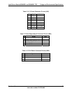
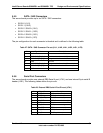
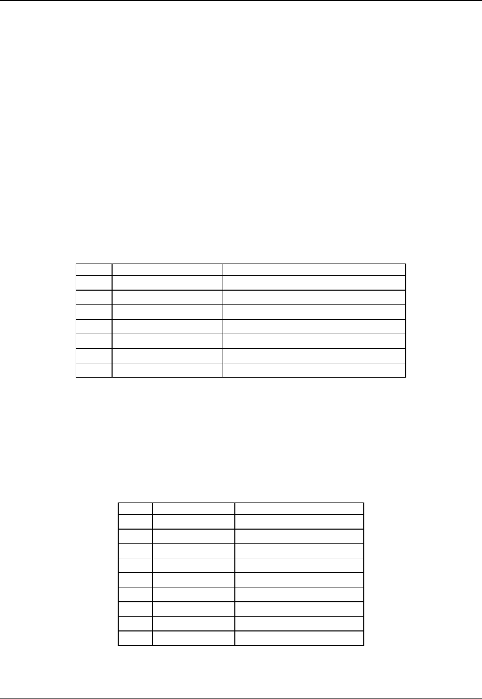
5.5.5 SATA / SAS Connectors
The server board provides up to six SATA / SAS connectors:
SATA-0 (J1J1)
SATA-1 (J1H2)
SATA-2 / SAS-0 (J1H1)
SATA-3 / SAS-1 (J1G2)
SATA-4 / SAS-2 (J1G1)
SATA-5 / SAS-3 (J1F2)
The pin configuration for each connector is identical and is defined in the following table.
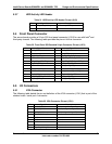
Table 27. SATA / SAS Connector Pin-out (J1J1, J1H2, J1H1, J1G2, J1G1, J1F2)
Pin Signal Name Description
1 GND Ground
2 SATA/SAS_TX_P_C Positive side of transmit differential pair
3 SATA/SAS_TX_N_C Negative side of transmit differential pair
4 GND Ground
5 SATA/SAS_RX_N_C Negative side of receive differential pair
6 SATA/SAS_RX_P_C Positive side of receive differential pair
7 GND Ground
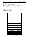
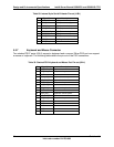
5.5.6 Serial Port Connectors
The server board provides one external DB9 Serial A port (J7A1) and one internal 9-pin serial B
header (J1B1). The following tables define the pin-outs.
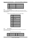
Table 28. External DB9 Serial A Port Pin-out (J7A1)
Pin Signal Name Description
1 SPA_DCD DCD (carrier detect)
2 SPA_SIN_L RXD (receive data)
3 SPA_SOUT_N TXD (Transmit data)
4 SPA_DTR DTR (Data terminal ready)
5 GND Ground
6 SPA_DSR DSR (data set ready)
7 SPA_RTS RTS (request to send)
8 SPA_CTS CTS (clear to send)
9 SPA_RI RI (Ring Indicate)