


Intel® Server Boards S5000PSL and S5000XSL TPS Design and Environmental Specifications
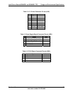
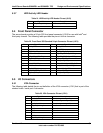
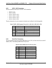
5.3.7 HDD Activity LED Header
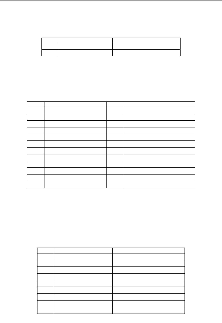
Table 21. HDD Activity LED Header Pin-out (J2J3)
Pin Signal Name Description
1 LED_SCSI_CONN_N HDD Activity LED Input
2 GND Ground
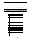
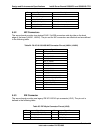
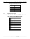
5.4 Front Panel Connector
The server board provides a 24-pin SSI front panel connector (J1E4) for use with Intel
®
and
third-party chassis. The following table provides the pin-out for this connector.
Table 22. Front Panel SSI Standard 24-pin Connector Pin-out (J1E4)
Pin Signal Name Pin Signal Name
1 P3V3_STBY 2 P3V3_STBY
3 Key 4 P5V_STBY
5 FP_PWR_LED_N 6 FP_ID_LED_BUF_N
7 P3V3 8 FP_LED_STATUS_GREEN_N
9 LED_HDD_ACTIVITY_N 10 FP_LED_STATUS_A MBER_N
11 FP_PWR_BTN_N 12 NIC1_ACT_LED_N
13 GND 14 NIC1_LINK_LED_N
15 BMC_RST_BTN_N 16 SMB_SENSOR_3V3STB_DATA
17 GND 18 SMB_SENSOR_3V3STB_CLK
19 FP_ID_BTN_N 20 FP_CHASSIS_INTRU
21 FM_SIO_TEMP_SENSOR 22 NIC2_ACT_LED_N
23 FP_NMI_BTN_N 24 NIC2_LINK_LED_N
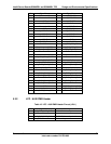
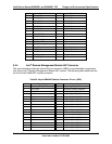
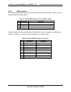
5.5 I/O Connectors
5.5.1 VGA Connector
The following table details the pin-out definition of the VGA connector (J7A1) that is part of the
stacked video / serial port A connector.
Table 23. VGA Connector Pin-out (J7A1)
Pin Signal Name Description
1 V_IO_R_CONN Red (analog color signal R)
2 V_IO_G_CONN Green (analog color signal G)
3 V_IO_B_CONN Blue (analog color signal B)
4 TP_VID_CONN_B4 No connection
5 GND Ground
6 GND Ground
7 GND Ground
8 GND Ground
9 TP_VID_CONN_B9 No connection
Revision 1.2
Intel order number: D41763-003
59