


Intel® Server Boards S5000PSL and S5000XSL TPS Design and Environmental Specifications
5. Connector / Header Locations and Pin-outs
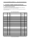
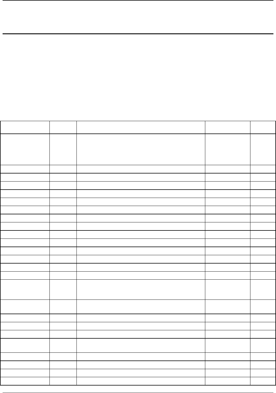
5.1 Board Connector Information
The following section provides detailed information regarding all connectors, headers and
jumpers on the server board.
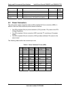
Table 10. Board Connector Matrix
lists all connector types available on the board and the corresponding reference designators
printed on the silkscreen.
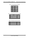
Table 10. Board Connector Matrix
Connector Quantity Reference Designators Connector Type Pin
Count
Power supply 4 J9B5
J3J2
J9D1
J5A2
Main power
CPU power
P/S aux / IPMB
P12V4 power
24
8
5
4
CPU 2 J8G1, J5G1 CPU sockets 771
Main memory 8 J7B1, J7B2, J7B3, J8B1, J8B2, J8B3, J9B1, J9B2 DIMM sockets 240
PCI-X 2 J1B2, J2B1 Card edge
PCI Express* x8 2 J2B2, J3B1 Card edge
PCI Express* x16 2 J4B2, J4B1 Card edge
Intel
®
RMM 1 J5B1 Mezzanine 120
RMM NIC 1 J3B2 Mezzanine 40
RAID Key 2 J1E1, J1D3 Key holder 3
IDE 1 J2J2 Shrouded header 40
System fans 4 J3H1, J3H2, J3H3, J3H4 Header 6
System fans 2 J9B3, J9B4 Header 4
CPU fans 2 J9J1, J5J1 Header 4
Battery 1 XBT4D1 Battery holder 3
Keyboard / mouse 1 J9A1 PS2, stacked 12
22
Stacked RJ45 /
2xUSB
2 JA6A1, JA6A2 External LAN
built-in magnetic
and dual USB
Stacked video /
verial port A
1 J7A1 External DSub /
DB9
24
Serial port B 1 J1B1 Header 10
Front panel 1 J1E4 Header 24
Internal USB 1 J3J1 Header 10
Internal USB 1 J3G1 Type A
connector
4
Chassis Intrusion 1 J1A1 Header 2
Serial ATA / SAS 6 J1G1, J1F2, J1H1, J1G2, J1J1, J1H2 Header 7
HSBP / SGPIO 4 J1J2, J1J7, J2H1, J1J5 Header 4
SES I2C 1 J1J3 Header 3
Revision 1.2
Intel order number: D41763-003
53