


Intel® Server Boards S5000PSL and S5000XSL TPS Design and Environmental Specifications
Revision 1.2
Intel order number: D41763-003
65
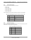
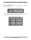
5.5.8 USB Connector
The following table details the pin-out of the external USB connectors (JA6A1, JA6A2) found on
the back edge of the server board.
Table 31. External USB Connector Pin-out (JA6A1, JA6A2)
Pin Signal Name Description
1 USB_OC USB_PWR
2 USB_PN DATAL0 (Differential data line paired with DATAH0)
3 USB_PP DATAH0 (Differential data line paired with DATAL0)
4 GND Ground
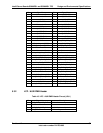
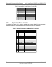
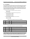
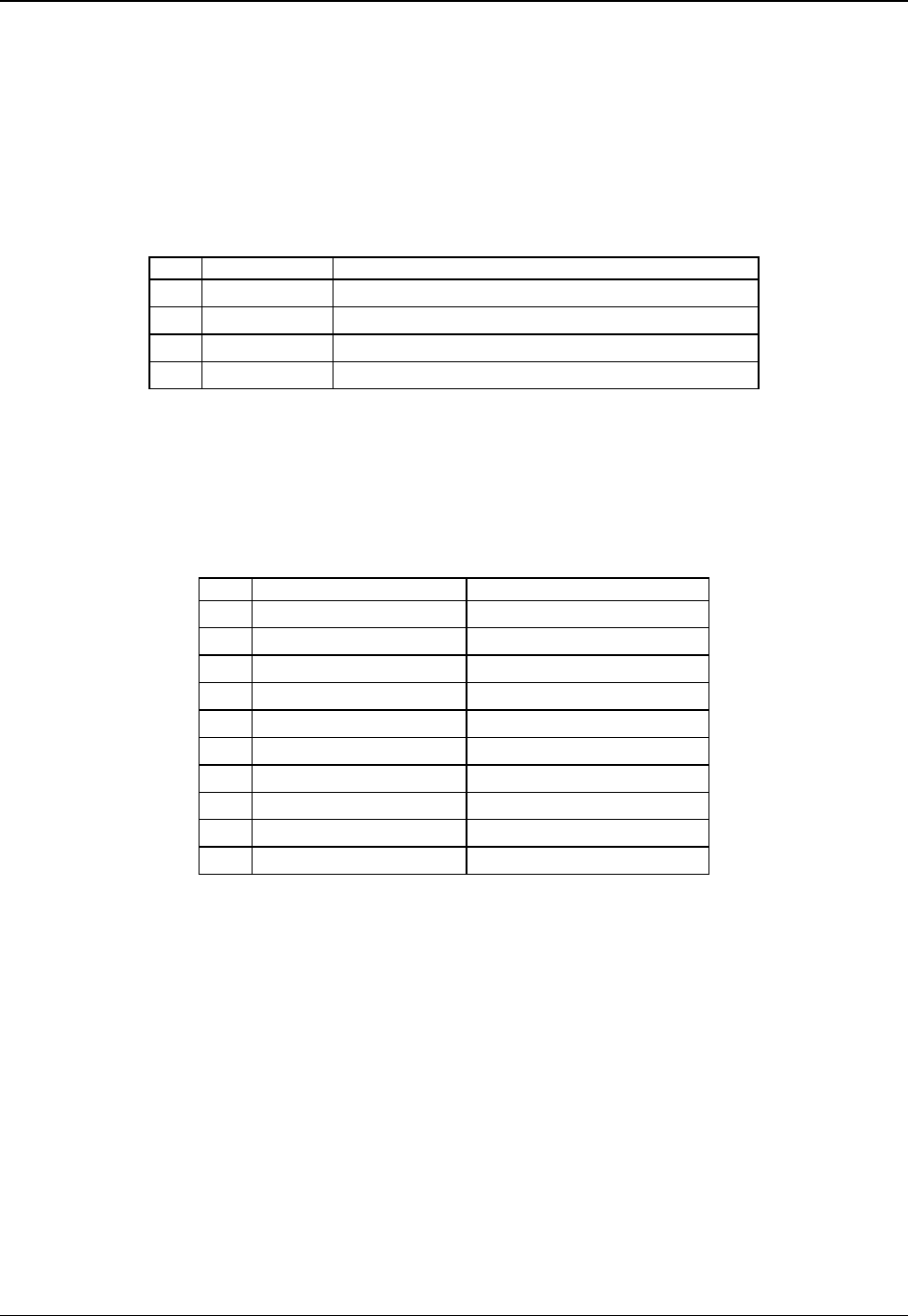
One 2x5 connector on the server board (J3J1) provides an option to support an additional two
USB ports. The pin-out of the connector is detailed in the following table.
Table 32. Internal USB Connector Pin-out (J3J1)
Pin Signal Name Description
1 USB2_VBUS5 USB power (port 5)
2 USB2_VBUS4 USB power (port 4)
3 USB_ESB_P5N_CONN USB port 5 negative signal
4 USB_ESB_P4N_CONN USB port 4 negative signal
5 USB_ESB_P5P_CONN USB port 5 positive signal
6 USB_ESB_P4P_CONN USB port 4 positive signal
7 Ground
8 Ground
9 Key No pin
10 TP_USB_ESB_NC Test point