


Intel® Server Boards S5000PSL and S5000XSL TPS Appendix A: Integration and Usage Tips
Appendix A: Integration and Usage Tips
When adding or removing components or peripherals from the server board, AC power
must be removed. With AC power plugged into the server board, 5-volt standby is still
present even though the server board is powered off.
Processors must be installed in order. CPU 1 is located near the edge of the server
board and must be populated to operate the board.
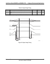
On the back edge of the server board are four diagnostic LEDs that display a sequence
of red, green, or amber POST codes during the boot process. If the server board hangs
during POST, the LEDs will display the last POST event run before the hang.
Only Fully Buffered DIMMs (FBDIMMs) are supported on this server board. For a list of
supported memory for this server board, see the Intel
®
S5000PSL / S5000XSL Tested
Memory List.
For a list of Intel supported operating systems, add-in cards, and peripherals for this
server board, see the Intel
®
S5000PSL / S5000XSL Tested Hardware and OS List.
Only Dual-Core Intel
®
Xeon
®
processors 5000 Series, with system bus speeds of 667,
1066, or 1333 MHz are supported on this server board. Previous generation Intel
®
Xeon
®
processors are not supported.
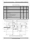
For the best performance, the number of FBDIMMs installed should be balanced across
both memory branches. For example: a four-DIMM configuration will perform better than
a two DIMM configuration. In a four-DIMM configuration, FBDIMMs should be installed in
DIMM sockets A1, B1, C1, and D1. An eight-DIMM configuration will perform better then
a six DIMM configuration.
The Intel
®
RMM connector is not compatible with the Intel
®
Server Management Module
Professional Edition (Product Code AXXIMMPRO) or with the Intel
®
Server Management
Module Advanced Edition (Product Code AXXIMMADV)
Removing AC power before performing the CMOS Clear operation will cause the system
to automatically power up and immediately power down after the CMOS Clear procedure
is followed and AC power is re-applied. If this happens, remove the AC power cord, wait
30 seconds, and then re-connect the AC power cord. Power up the system and proceed
to the <F2> BIOS Setup Utility to reset the desired settings.
Normal BMC functionality is disabled with the force BMC update jumper set to the
“enabled” position (pins 2-3). The server should never be run with the BMC force update
jumper set in this position and should only be used when the standard firmware update
process fails. This jumper should remain in the default (disabled) position (pins 1-2)
when the server is running normally.
When performing a BIOS update procedure, the BIOS select jumper must be set to its
default position (pins 2-3).
Revision 1.2
Intel order number: D41763-003
93