


Design and Environmental Specifications Intel® Server Boards S5000PSL and S5000XSL TPS
Revision 1.2
Intel order number: D41763-003
64
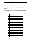
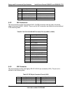
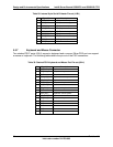
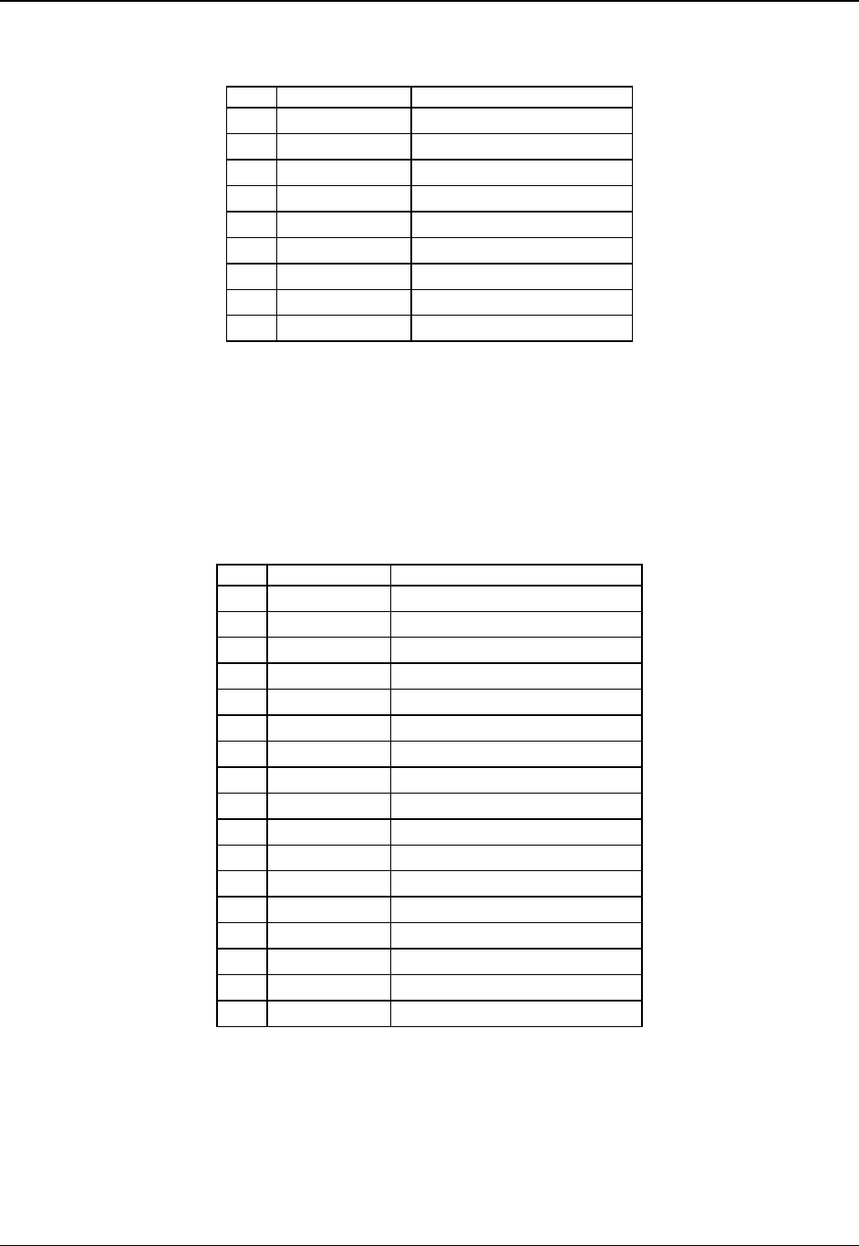
Table 29. Internal 9-pin Serial B Header Pin-out (J1B1)
Pin Signal Name Description
1 SPB_DCD DCD (carrier detect)
2 SPB_DSR DSR (data set ready)
3 SPB_SIN_L RXD (receive data)
4 SPB_RTS RTS (request to send)
5 SPB_SOUT_N TXD (Transmit data)
6 SPB_CTS CTS (clear to send)
7 SPB_DTR DTR (Data terminal ready)
8 SPB_RI RI (Ring indicate)
9 SPB_EN_N Enable
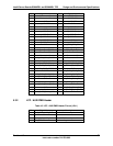
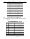
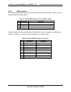
5.5.7 Keyboard and Mouse Connector
Two stacked PS/2* ports (J9A1) support a keyboard and a mouse. Either PS/2 port can support
a mouse or keyboard. The following table details the pin-out of the PS/2 connectors.
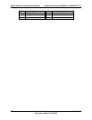
Table 30. Stacked PS/2 Keyboard and Mouse Port Pin-out (J9A1)
Pin Signal Name Description
1 KB_DATA_F Keyboard data
2 TP_PS2_2 Test point – keyboard
3 GND Ground
4 P5V_KB_F Keyboard / mouse power
5 KB_CLK_F Keyboard clock
6 TP_PS2_6 Test point – keyboard / mouse
7 MS_DAT_F Mouse data
8 TP_PS2_8 Test point – keyboard / mouse
9 GND Ground
10 P5V_KB_F Keyboard / mouse power
11 MS_CLK_F Mouse clock
12 TP_PS2_12 Test point – keyboard / mouse
13 GND Ground
14 GND Ground
15 GND Ground
16 GND Ground
17 GND Ground